


8To reconfigure a channel based on your actual channel requirements, enter commands as described in Chapter 5 of
this manual. To save new parameters, you must again execute an AT&W command.
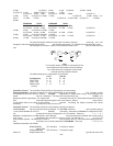
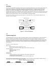
9If you are downline loading remote parameters, 8-position DIP switch SW1 must be in the UP (open) position; refer to
the 8-position DIP Switch in the Configuration Chapter (Chapter 3) of this manual. The other mux in
your network must be configured properly and have its 8-position DIP switch SW1 in the DOWN
(closed) position. You then can execute a Reset command (Z) to send the new parameters to your
remote mux.
10To return to local parameter display and control, execute a Select Local Parameter command by entering the
following:
AT&SL (hit Return)
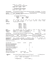
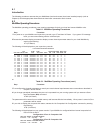
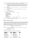
11To use the status display and auto reporting feature, execute the Status Reporting command by entering the
following:
AT#A/BS0 (hit Return)
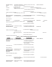
The following will be displayed on your system monitor:
COMPOSITE STATISTICS
ELAPSED TIME : 00 DAYS 00 HRS 00 MIN.
DATA BLOCKS TRANSMITTED : 0
DATA BLOCKS RETRANSMITS : 0
DATA BLOCKS RECEIVED : 0
RECEIVE BLOCK ERRORS : 0
VOICE/FAX BLOCKS TRANSMITTED : 0
VOICE/FAX BLOCKS RECEIVED : 0
LINK ALARMS : 0
REMOTE DOWNS : 0
LINK UTILIZATION : 0%
RECEIVE FLOW CONTROL TIME : 00 HRS 00 MIN 00 SEC.
AUTOMATIC REPORTING : OFF 19200 BAUD
To select the bps rate and time interval at which the above status screen will appear, execute a #RBxx and #RTxx
commands as described in Chapter 5 of this manual.
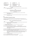
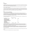
6.3
Voice/Fax Operating Procedures
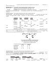
The Voice/Fax Operating Procedures begin with displaying the Voice/Fax Channel parameters and then executing the
commands to change the default parameters to fit your specific voice or fax needs. The Voice/Fax Channel parameters
are displayed for both channels and contain general parameters for each channel such as destination channel number
through silence suppression. The local and remote interface types define the specific type of interface and the
conditions that govern that interface. Not all the parameters for a particular interface apply, such as 2 or 4-wire, and
dialtone or wink do not apply for an FXO interface. To change a default Voice/Fax Channel parameter, refer to the
Voice/Fax Channel Commands in Chapter 5.
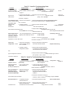
Table 6-2. Voice/Fax Operating Procedures
Step Procedure
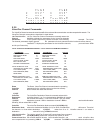
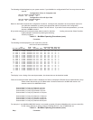
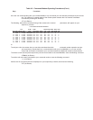
1If you wish to display the Voice/Fax Channel Parameters, execute the List The Voice/Fax Channel Parameters
command by entering the following:
ATVL (hit Return)
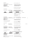
The following will be displayed on your system monitor:
LOCAL VOICE/FAX PARAMETERS CHANNEL1 LOCAL VOICE/FAX PARAMTERS CHANNEL 2
PARAMETER STATUS PARAMETER STATUS
DESTINATION CHANNEL: 01 DESTINATION CHANNEL: 02
DESTINATION NODE: 01 DESTINATION NODE: 01
LINK A/B/D: A LINK A/B/D: A
DIGITIZING RATE: 16000 DIGITIZING RATE: 16000
OUTPUT LEVEL ATTEN.: 12 OUTPUT LEVEL ATTEN.: 12
INPUT LEVEL GAIN: 03 INPUT LEVEL GAIN: 03
SILENCE SUPPRESSION: 00 SILENCE SUPPRESSION: 00
LOCAL INTERFACE TYPE: FXS LOCAL INTERFACE TYPE: FXS
GROUND/LOOP START (FXS): LOOP GROUND/LOOP START (FXS): LOOP
2 OR 4 WIRE (E&M): 2 WIRE 2 OR 4 WIRE (E&M): 2 WIRE