


2.3
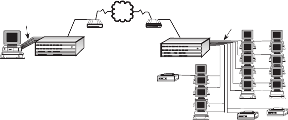
Configuration 2
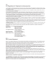
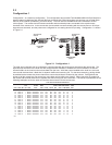
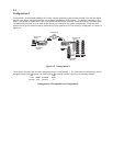
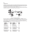
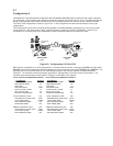
Configuration 2 is two MultiMux MMV1616C sixteen channel multiplexers with two external Multi-Tech 56K bps Digital
Service Units (DSUs) linking the two sites over a Digital Data Service (DDS) network. The RS232C interface on The
DSUs is connected to COMPOSITE LINK A EXTERNAL MODEM/DSU connector on the back panel of the MMV1616C.
The MMV1616Cs are set up for an external link device with a maximum link speed of 56,000 bps. Composite link A
needs to be set up for external clocking. Both external DSUs must be set for DDS clocking. Configuration 2 is shown in
Figure 2-2.
Channel 9 Channel 10 Channel 11 Channel 12
Channel 13 Channel 14 Channel 15
Channel 16
Channel 1 Channel 2
Channel 3 Channel 4
Channel 5 Channel 6 Channel 7 Channel 8
Composite Link A Composite Link B
Command Modem
Voice/Fax Channel 1
Voice/Fax Channel 2
MultiMux 16
Data/Voice/Fax
Statistical Multiplexer
Systems
MultiTech
®
Local Site
MultiMux MMV1616
Asynchronous
Channel
Unix Host
PDN
Dial-Up Line
Composite Link
MT56DSU
2
MT56DSU
2
(Node 1)
MultiMux MMV1616
Channel 9 Channel 10 Channel 11 Channel 12
Channel 13 Channel 14 Channel 15
Channel 16
Channel 1 Channel 2
Channel 3 Channel 4
Channel 5 Channel 6 Channel 7 Channel 8
Composite Link A Composite Link B
Command Modem
Voice/Fax Channel 1
Voice/Fax Channel 2
MultiMux 16
Data/Voice/Fax
Statistical Multiplexer
Systems
MultiTech
®
Asynchronous
Channel
Printer
Remote Site
Printer
Terminal
Terminal
Printer
Printer
Terminal
(Node 2)
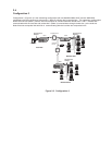
Figure 2-2. Configuration 2
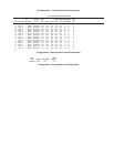
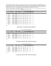
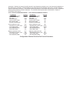
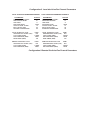
The channels are set up with the same considerations as in Configuration 1. The composite link configuration may be
changed using the List Composite Link Configuration ($L) command which is shown in the following example.
DSU LOOP
TYPE SPEED CLOCKING BACK
EXTERNAL 56000 EXTERNAL OFF
Configuration 2 Composite Link Configuration