


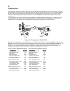


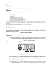
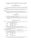

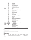
Figure 4-2. Composite Link Cabling
2 Loosen the two pc board chassis lock screws on the back panel. See Figure 4-2.
3 Pry up on the two pc board chassis lock screws to unlock the pc boards in the chassis. Temporarily retighten
these screws while in the up position.
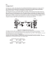
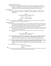
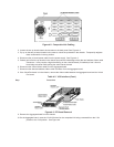
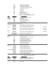
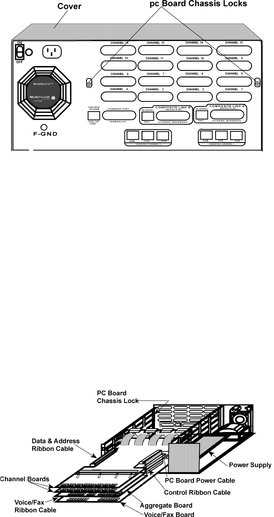
4 Disconnect the pc board power cable from the power supply. See Figure 4-3.
5 Partially pull out all the pc boards in the chassis just past the inside edge of the data and address ribbon cable
connectors. It may require a slight forward tug on the voice/fax board (if installed) to free it from its
board edge connector while pulling the other boards forward.
6 Disconnect the control ribbon cable from the Aggregate board.
7 Disconnect the data and address ribbon cable connector from the Aggregate board.
8 If the Voice/Fax board is in the chassis, remove the ribbon cable between the Aggregate board and the Voice/
Fax board.
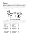
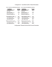
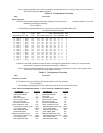
Table 4-2. V.35 Interface (Cont.)
Step Procedure
Figure 4-3. PC Board Removal
9 Remove the Aggregate board from the chassis.
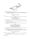
10 On the Aggregate board, move the V.24/V.35 shunt for the composite link being connected from the V.24
position to the V.35 position. See Figure 4-4.