9-28 User’s Reference Guide
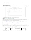
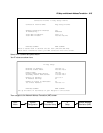
■ First, navigate to the Show/Change Map List screen, select Easy-PAT List and then Show/Change Maps.
Choose the Static Map you created and change the First Private Address from 192.168.1.1 to
192.168.1.4. Now the router, Web, and Mail servers’ IP addresses are no longer included in the range of
static mappings and are therefore no longer accessible to the outside world. Users on the Internet will not
be able to telnet, web, SNMP or ping to them. It is best also to navigate to the public range screen and
change the Static Range to go from 206.1.1.5.
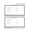
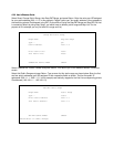
■ Next, navigate to Show/Change Server List and select Easy-Servers and then Add Server. You should
export both the Web (www-http) and Mail (smtp) ports to one of the now free public addresses. Select
Service... and from the resulting pop-up menu select www-http. In the resulting screen enter your Web
server's address, 192.168.1.2 and the public address, for example, 206.1.1.2 and then select ADD NAT
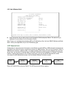
SERVER. Now return to Add Server, choose the smtp port and enter 192.168.1.3, your Mail server's IP
address for the Server Private IP Address. You can decide if you want to present both your Web and Mail
services as being on the same public address, 206.1.1.2, or if you prefer to have your Mail server appear
to be at a different IP address, 206.1.1.3. For the sake of this example, alias both services to 206.1.1.2.
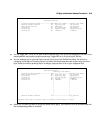
Now, as before, the PAT configuration will allow any user on the Netopia R310's LAN with an IP address in the
range of 192.168.1.6 through 192.168.1.254 to initiate traffic flow to the Internet. Someone at the FTP server
can access the Internet and the Internet can access all services of the FTP machine as if it were at 206.1.1.5.
The router cannot directly communicate with the outside world. The only communication between the Web
server and the Internet is through port 80, the web port, as if the server were located on a machine at IP
address 206.1.1.2. Similarly, the only communication with the Mail server is through port 25, the SMTP port,
as if it were located at IP address 206.1.1.2
IP subnets
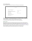
The IP Subnets screen allows you to configure up to eight Ethernet IP subnets, one “primary” subnet and up to
seven secondary subnets, by entering IP address/subnet mask pairs:
IP Subnets
IP Address Subnet Mask
---------------- ---------------
#1: 192.128.117.162 255.255.255.0
#2: 0.0.0.0 0.0.0.0
#3:
#4:
#5:
#6:
#7:
#8:


