


7–Removal and Replacement
Power and Cooling Modules
ISR651101-00 G 7-11
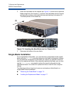
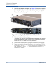
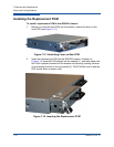
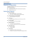
Figure 7-9. Back Side of Two PCMs with Fault (left) and Good (right) Status
Indicators
2. Check the second (GOOD) PCM to make sure it is ready to support storage
connectivity while you are replacing the failed PCM unit. Make sure the
second PCM’s power cable is connected to the cable with the other end
plugged into a live power source, and that it shows a green status LED.
3. Remove the power cable from the failed PCM unit. The LED remains amber
even after the removing the power cable.
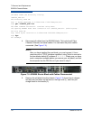
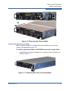
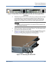
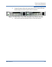
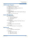
4. Release the chassis latch on the left side of the unplugged PCM. As shown
in Figure 7-10, pull down on the lever to unseat the PCM (1), and then
remove the PCM by pulling straight back on the handle (2).
Figure 7-10. Removing the Failed PCM
CAUTION!
Failure to verify the functionality of the second PCM can result in lost
host storage connectivity.
(2)
(1)