


1–Introduction
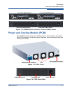
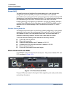
Power and Cooling Module (PCM)
ISR651101-00 G 1-3
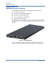
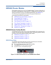
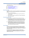
Figure 1-2. iSR6200 Router Chassis—Front and Back Plates
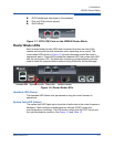
Power and Cooling Module (PCM)
Each iSR6200 chassis blade has a PCM located on the backside of the chassis.
Each PCM consists of one power supply, three fans, and one external status light
emitting diode (LED).
Figure 1-3. PCM—Front
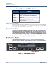
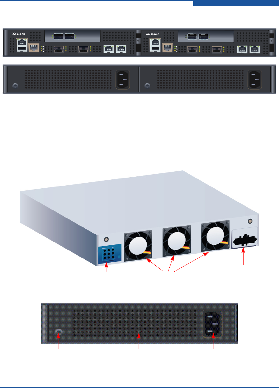
Figure 1-4. PCM—Back Plate
MGMT IOIOI
FC1 FC2
MGMT IOIOI
FC1 FC2
10GbE1 iSR6250
Intelligent Storage Router
10GbE2
10GbE1 iSR6250
Intelligent Storage Router
10GbE2
Front Plate iSR6200 Blade 1 Front Plate iSR6200 Blade 2
Back Plate PCM for Blade 2 Back Plate PCM for Blade 1
Fans & Temperature Sensors
Mid-Plane Power Connector
Connector to Power Supply
and Temperature Sensors
Fans
PCM Status Indicator Fan Exhaust Grill Power Connector