


1–Introduction
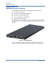
iSR6200 Router Blades
1-8 ISR651101-00 G
Input Power LED (Green)
The power LED shows the voltage status of the router logic circuit board. During
normal operation, this LED lights up to show that the router logic circuit board is
receiving the DC voltage from the power supply.
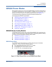
Beacon Indicator (Blue)
The iSR6200 router blade’s printed circuit board (PCB) has a blue beacon light
installed near the center vent hole between the Fibre Channel ports (Figure 1-8).
This light enables you to locate the physical blade when monitoring the iSR6200
routers using SANsurfer Router Manager. If you enable the Beacon On option for
a selected blade in SANsurfer Router Manager, the blue beacon light flashes
through the vent hole on the chassis blade’s faceplate.
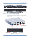
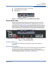
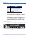
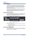
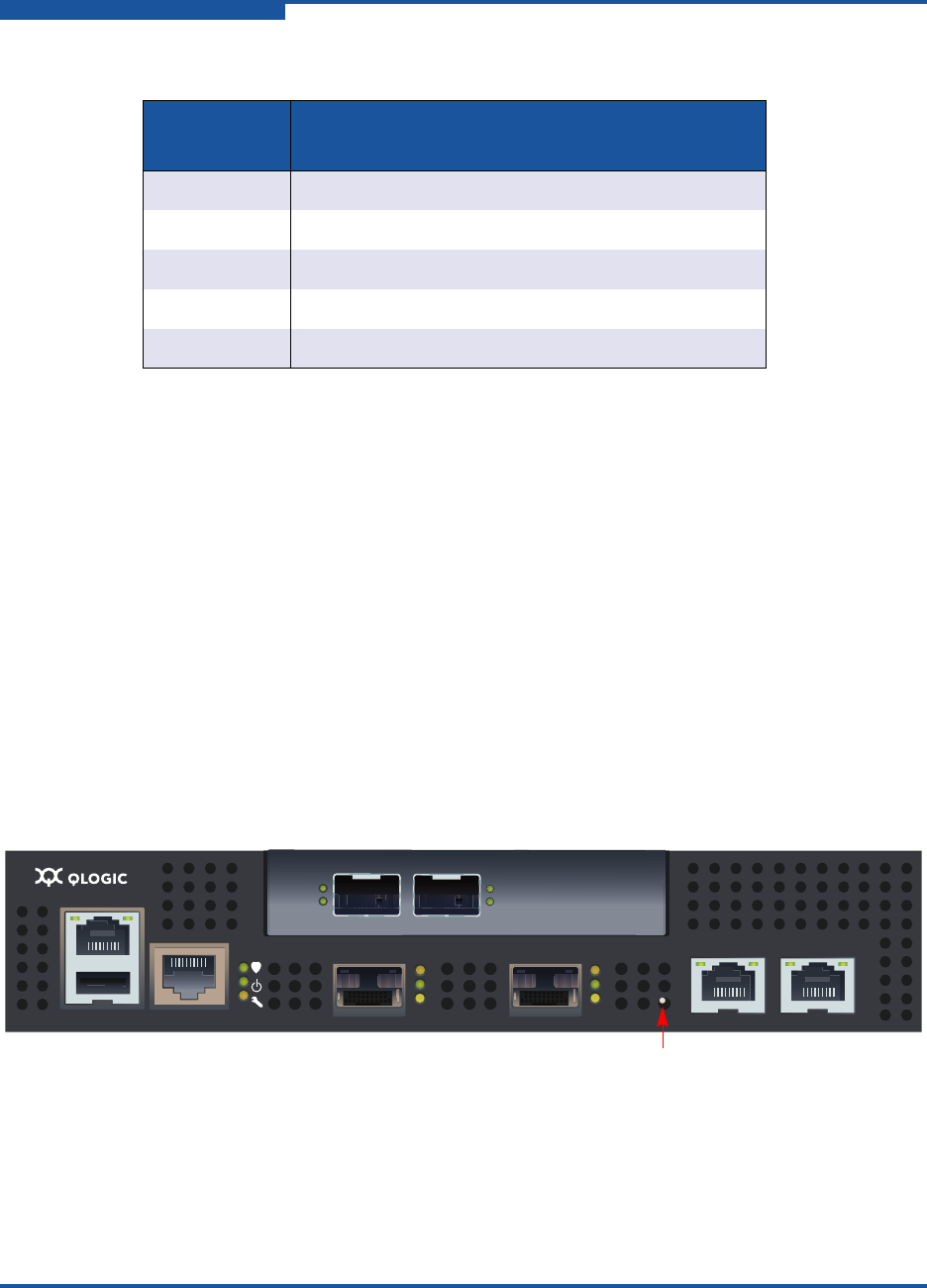
Maintenance Button
The maintenance button shown in Figure 1-9 is the only router blade control.
Press this button to reset the router blade or to recover it if it becomes disabled.
Figure 1-9. Router Blade Controls
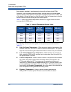
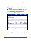
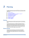
Table 1-3. System Fault LED Blink Patterns
System
Fault LED
Condition
OFF OK (operational)
1 Blink Beacon; synchronized with the heartbeat LED
3 Blinks System error
4 Blinks Management port IP address conflict
5 Blinks Over-temperature
MGMT IOIOI
FC1 FC2 GE1 GE1
GE4 GE3 iSR6240
Intelligent Storage Router
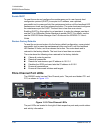
iSR6200 System
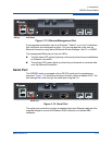
10GbE1 iSR6250
Intelligent Storage Router
10GbE2
Maintenance Button