


3–Installation
Installing the iSR6200 Router
ISR651101-00 G 3-7
Connecting the Router to AC Power
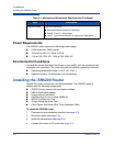
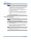
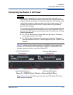
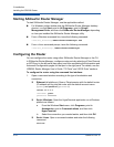
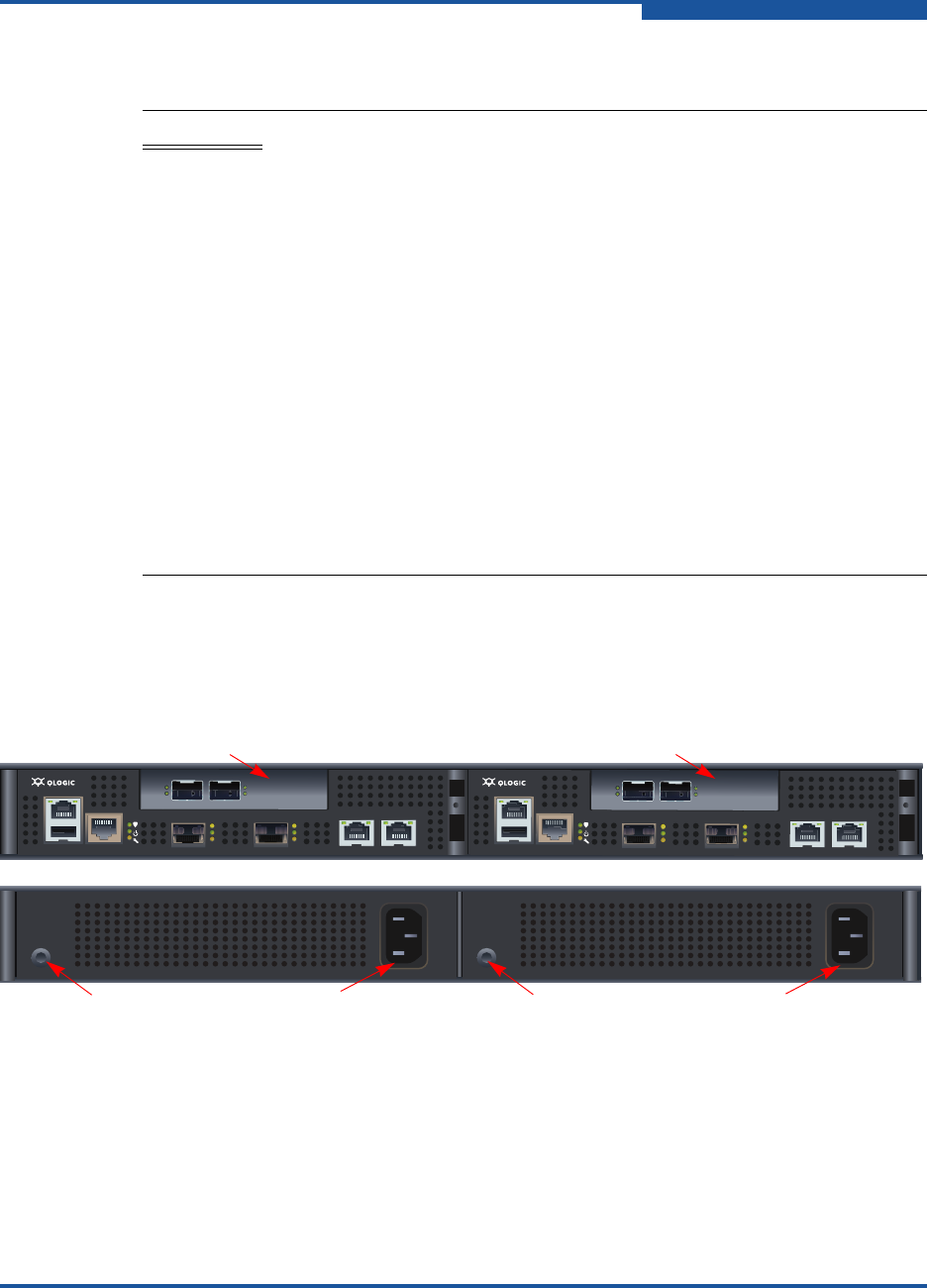
Figure 3-1 shows the front and back plates of an iSR6200 router chassis that
contains two router blades with add-in ports installed for its model. Each PCM
provides a power connector, as well as a Status LED.
Figure 3-1. iSR6200 Router Chassis—Front and Back Plates
Refer to Figure 3-1 to locate the power connector and PCM status LED for the
blade you are configuring.
WARNING!!
This product is supplied with a three-wire power cable and plug for the
user’s safety. Use this power cable in conjunction with a properly grounded
outlet to avoid electrical shock. An electrical outlet that is not correctly wired
could place hazardous voltage on metal parts of the router chassis. The
customer must make sure the outlet is correctly wired and grounded to
prevent electrical shock.
You may require a different power cable in some countries because the plug
on the cable supplied with the equipment will not fit your electrical outlet. In
this case, you must supply your own power cable. The cable must meet the
following requirements:
For 125 volt electrical service: the cable must be rated at 10 amperes
and be approved by UL and CSA.
For 250 volt electrical service: the cable must be rated at 10 amperes,
meet requirements of H05VV-F, and be approved by VDE, SEMKO, and
DEMKO.
MGMT IOIOI
FC1 FC2
MGMT IOIOI
FC1 FC2
10GbE1 iSR6250
Intelligent Storage Router
10GbE2
10GbE1 iSR6250
Intelligent Storage Router
10GbE2
Expansion Slot
Front Plate iSR6200 Blade 1
Front Plate iSR6200 Blade 2
Back Plate PCM for Blade 2
Back Plate PCM for Blade 1
Expansion Slot
PCM Status LED PCM Status LEDPower Connector Power Connector