


1–Introduction
iSR6200 Router Blades
1-12 ISR651101-00 G
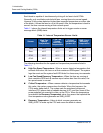
The iSR6200 router supports SFP optical transceivers for the Fibre Channel ports.
A transceiver converts electrical signals to and from optical laser signals to
transmit and receive data. Duplex fiber optic cables plug into the transceivers,
which then connect to the devices. For example, a 2Gbps or 4Gbps Fibre Channel
port can transmit at 2Gbps or 4Gbps; however, the transceiver must also be
capable of delivering these rates.
The SFP transceivers are hot pluggable. You can remove or install a transceiver
while the router is operating without harming the router or the transceiver.
However, this interrupts communication with the connected device. For details
about installing and removing SFP optical transceivers, see “Installing the
Transceivers” on page 3-6.
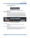
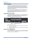
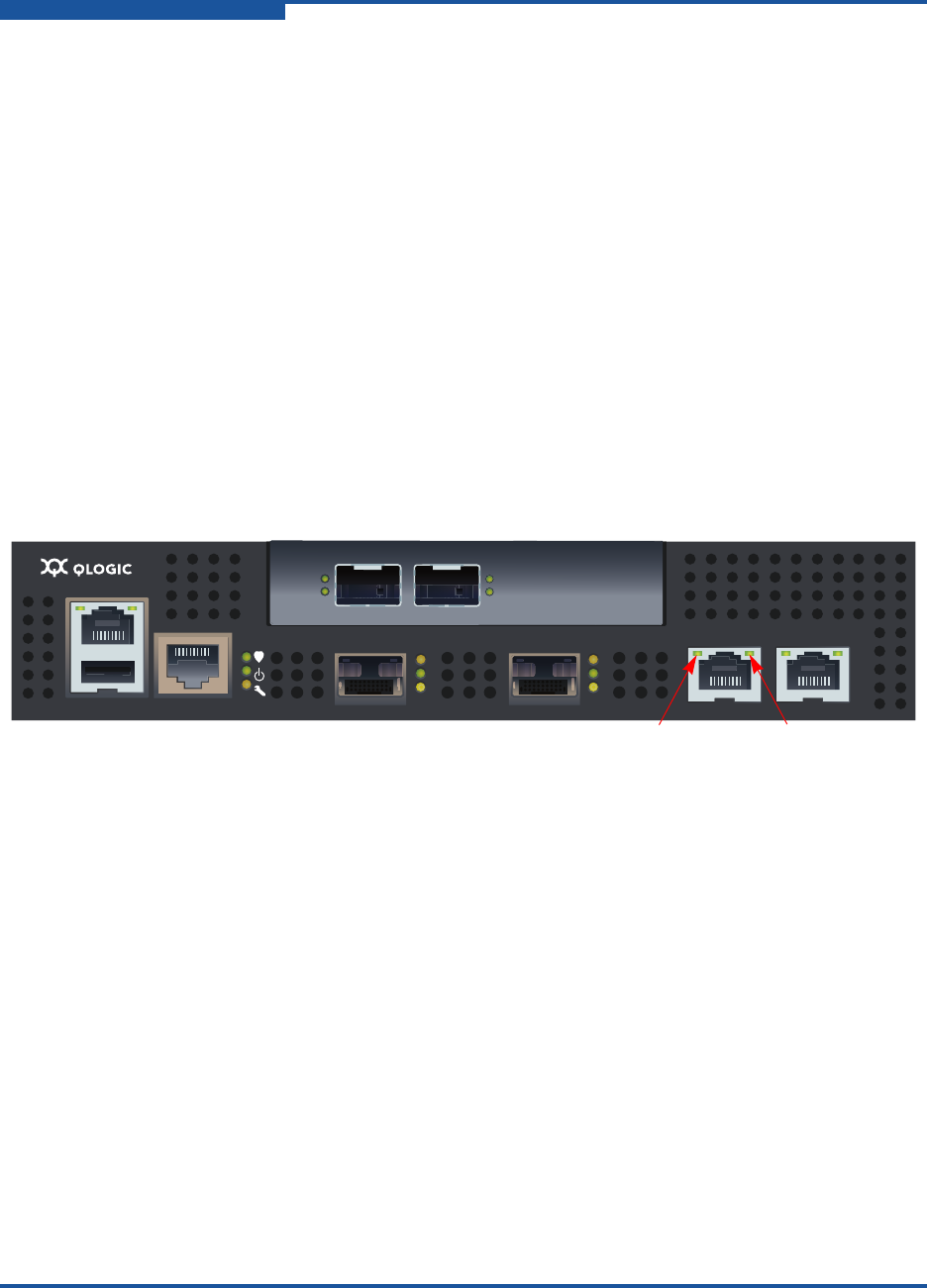
Gigabit Ethernet Port LEDs
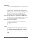
The gigabit Ethernet (GbE) ports shown in Figure 1-11 are RJ45 connectors that
provide connection to an Ethernet SAN through a 100 or 1000 Base-T Ethernet
cable. The ports are labeled GE1 and GE2. Each of these ports supports
connections that run the iSCSI high-level TCP protocol.
Figure 1-11. Gigabit Ethernet Ports
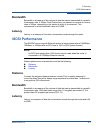
GbE ports each have two LEDs:
The activity LED (green) lights up when the port transmits or receives data
over the Ethernet connection.
The link status LED (green) lights up continuously when the port establishes
an Ethernet connection.
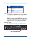
Ethernet Port—Management
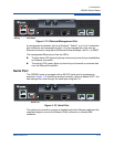
The management Ethernet port shown in Figure 1-12 is an RJ45 connector that
provides a connection to a management workstation through a 10 or 100 Base-T
Ethernet cable. The port is labeled MGMT.
MGMT IOIOI
FC1 FC2 GE1 GE1
GE4 GE3 iSR6240
Intelligent Storage Router
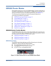
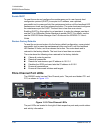
iSR6200 System
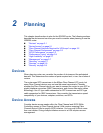
10GbE1 iSR6250
Intelligent Storage Router
10GbE2
Activity Link Status