


3–Installation
Installing the iSR6200 Router
3-8 ISR651101-00 G
To power on the router:
1. Attach the AC power cord to the power connector, located on the back side
of the PCM connected directly behind the router blade.
2. Connect the opposite end of the power cord to a grounded AC wall outlet or
power strip.
3. Check the PCM power LED to make sure the fan is operational (green = OK,
yellow = no AC power).
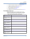
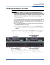
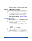
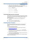
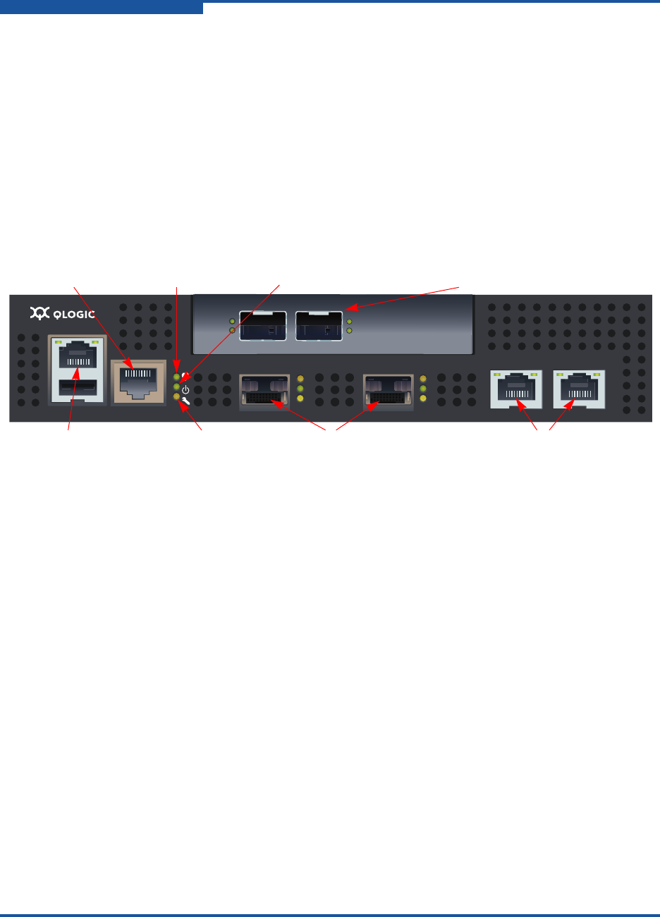
Figure 3-2 shows the location of the ports and LEDs on one of the blades
contained within the iSR6200 unit that are referenced in the following
instructions.
Figure 3-2. iSR6200 Blade Ports and LEDs
4. Verify that the router’s input power LED is illuminated.
The iSR6200 router runs its self test and begins normal operation—this may
take a minute.
5. Verify that the heartbeat LED is blinking (once per second) and that the
system fault LED is not illuminated.
If an error has occurred, the system fault LED blinks a pattern that indicates the
fault reason. For more information about error blink patterns, see page 6-2.
Connecting the Management Workstation to the Router
You can manage the router using either SANsurfer Router Manager or the CLI.
SANsurfer Router Manager requires an Ethernet connection to the router. The CLI
can use either an Ethernet connection or a serial connection. Choose the router
management method, and then connect the management workstation to the
router in one of the following ways:
Indirect Ethernet connection from the management workstation to the
router RJ45 connector through an Ethernet switch or hub. This requires a 10
or 100 Base-T straight cable.
MGMT IOIOI
FC1 FC2 GE1 GE1
GE4 GE3 iSR6240
Intelligent Storage Router
iSR6200 System
10GbE1 iSR6250
Intelligent Storage Router
10GbE2
Management Port System Fault LED
RS232 Port Heartbeat LED Power LED
Fibre Channel Ports iSCSI Ports
Expansion Ports Based on Model