1–Introduction
iSR6200 Router Blades
ISR651101-00 G 1-11
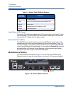
Each port has three LEDs:
The amber (top) LED shows activity for data passing through the port at
2Gbps speed.
The green LED (middle) shows activity for data passing through the port at
4Gbps speed.
The yellow LED (bottom) shows activity for data passing through the port at
8Gbps speed.
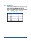
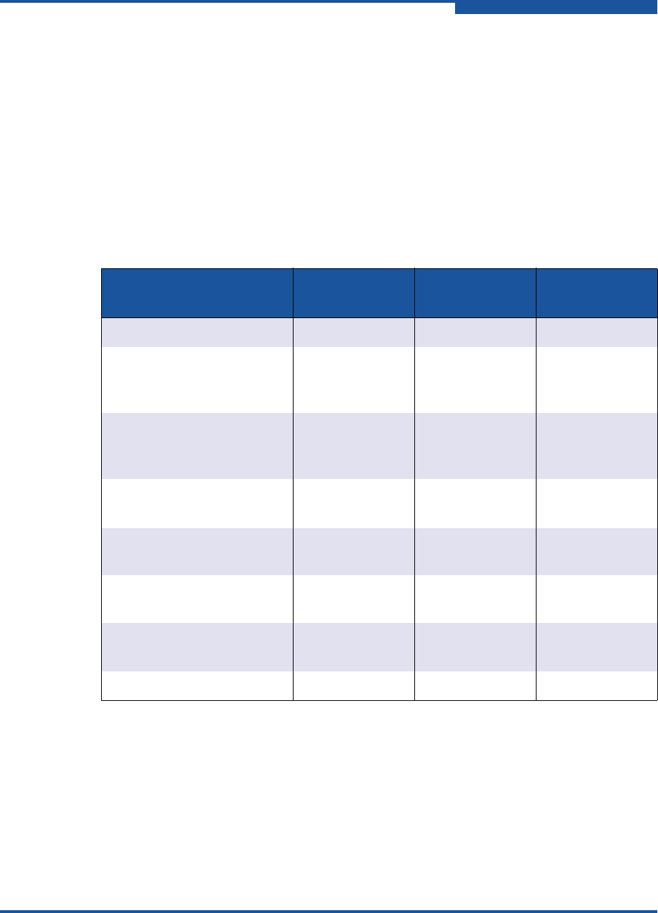
Table 1-4 describes the port LED blink patterns and their meanings.
Fibre Channel Transceivers
Each port is served by an SFP optical transceiver and is capable of 2, 4, or 8Gbps
transmission. SFPs are hot-pluggable. User ports can self-discover both the port
type and transmission speed when connected to public devices or switches.
Table 1-4. Port LEDs
Activity
Yellow LED
(8Gbps)
Green LED
(4Gbps)
Amber LED
(2Gbps)
Power OFF
OFF OFF OFF
Power ON
(before firmware initializa-
tion)
ON ON ON
Power ON
(after firmware initializa-
tion)
Flashing Flashing Flashing
Firmware initialization
error
a
a
Yellow, green, and amber LEDs flash alternatively to indicate firmware initialization errors.
Alternate
flashing
Alternate
flashing
Alternate
flashing
Online, 2Gbps link—I/O
activity
OFF OFF ON and flashing
Online, 4Gbps link—I/O
activity
OFF ON and flashing OFF
Online, 8Gbps link—I/O
activity
ON and flashing OFF OFF
Beacon
Flashing OFF Flashing


