


UGR003/0900 UCR-150L Robot
INSTALLATION 3-7
IMPORTANT: Always refer to
the wiring diagrams that
came with your robot before
making electrical connec-
tions. The diagrams show the
minimum size main power
cable required for your robot,
and the most accurate electri-
cal component information.
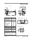
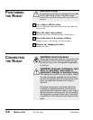
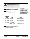
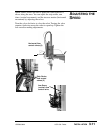
Plug the hand-held control into the control
box on the back of the robot.
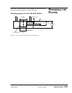
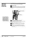
Check to see what the power output is from
the IMM to the robot. You need to tap wires so that power
can go to the IMM SPI half 30 and 31:
1
2
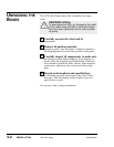
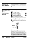
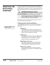
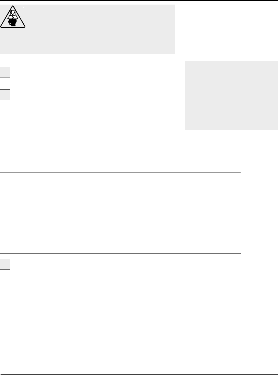
WARNING: Crushing Injury
This device has high speed moving parts that
can cause crushing injuries. Keep body parts
and clothing away from moving parts. Always
disconnect the robot from compressed air
sources before servicing.
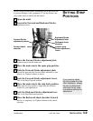
Connect the SPI connector cable into the
SPI connector on the robot control box and to the SPI
connector on the mold machine.
For IMM Output
Voltage:
110VAC / 1 phase
240VAC / 1 phase
240VAC / 3 phase
Choose:
1 neutral wire and
1 hot wire
1 ground wire
1 L wire
1 N wire
X, Y, and Z wires or
R, S, and T wires
(depends on your IMM)
Place into:
Place into Positions 30 and 31 of
SPI IMM half connector.
Place L and N wires into Positions
30 and 31 of SPI IMM half connector
(in any order) do not wire Ground
wire.
Choose any two wires and connect
into Positions 30 and 31 of the IMM
SPI half connector.
3