


Be aware that running the motor at a low speed for a long time can cause motor
overheating. This is particularly true when manual torque boost is ON, or if the motor
relies on a built-in fan for cooling.
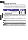
V
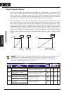
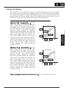
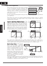
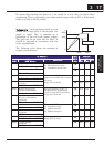
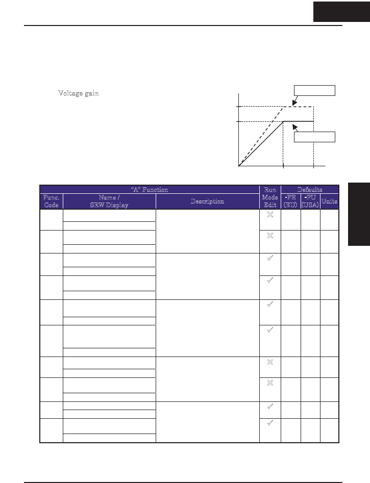
oltage gain – Using parameter A045 you can
modify the voltage gain of the inverter (see
graph at right). This is specified as a
percentage of the full scale output voltage.
The gain can be set from 20% to 100%. It
should be adjusted in accordance with the
motor specifications.
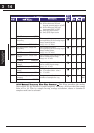
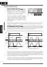
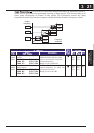
The following table shows the methods of
torque control selection.
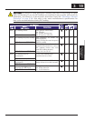
“A” Function Defaults
Func.
Code
Name /
SRW Display
Description
Run
Mode
Edit
-FE
(EU)
-FU
(USA)
Units
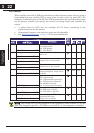
Torque boost selectA041
V-Bst Slct MN
U
00 00 %
Torque boost select, 2
nd
motorA241
2VBst Slct MN
Two options:
00}Manual torque boost
01}Automatic torque boost
U
00 00 %
Manual torque boost valueA042
V-Bst V 0005.0%
9
1.8 1.8 %
Manual torque boost value,
2
nd
motor
A242
2VBst V 0005.0%
Can boost starting torque
between 0 and 20% above normal
V/f curve,
range is 0.0 to 20.0%
9
0.0 0.0 %
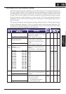
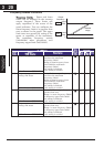
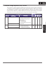
Manual torque boost
frequency adjustment
A043
M-Bst F 0003.0%
9
10.0 10.0 %
Manual torque boost
frequency adjustment,
2nd motor
A243
2MBst F 0000.0%
Sets the frequency of the V/f
breakpoint A in graph (top of
previous page) for torque boost,
range is 0.0 to 50.0%
9
0.0 0.0 %
V/f characteristic curveA044
CTRL C-TRQ
U
00 00
V/f characteristic curve,
2nd motor
A244
2CTRL C-TRQ
Two available V/f curves;
00}Constant torque
01}Reduced torque
06}Reduced torque1
U
00 00
V/f gain settingA045
V-Gain 00100%
9
100. 100. %
V/f gain setting,
2nd motor
A245
2V-Gain 00100%
Sets voltage gain of the inverter,
range is 20. to 100.%
9
100. 100. %
100%
fbase
fmax
A045=100
80%
A045=80
V
0
317
3 17
&RQ¿JXULQJ'ULYH
Parameters