


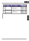
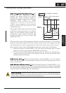
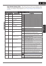
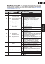
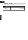
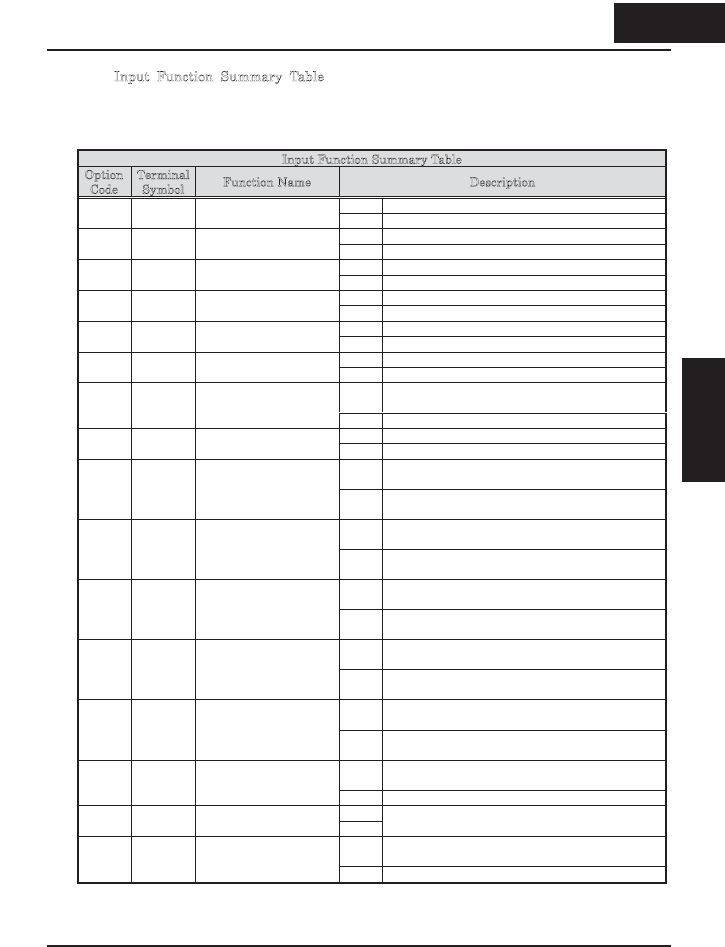
Input Function Summary Table – This table shows all thirty-one intelligent input
functions at a glance. Detailed description of these functions, related parameters and
settings, and example wiring diagrams are in “Using Intelligent Input Terminals” on
page 4-8.
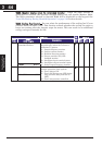
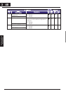
Input Function Summary Table
Option
Code
Terminal
Symbol
Function Name Description
ON Inverter is in Run Mode, motor runs forward00 FW FORWARD Run/Stop
OFF Inverter is in Stop Mode, motor stops
ON Inverter is in Run Mode, motor runs reverse01 RV Reverse Run/Stop
OFF Inverter is in Stop Mode, motor stops
ON Binary encoded speed select, Bit 0, logical 102 CF1 *1 Multi-speed Select,
Bit 0 (LSB)
OFF Binary encoded speed select, Bit 0, logical 0
ON Binary encoded speed select, Bit 1, logical 103 CF2 Multi-speed Select,
Bit 1
OFF Binary encoded speed select, Bit 1, logical 0
ON Binary encoded speed select, Bit 2, logical 104 CF3 Multi-speed Select,
Bit 2
OFF Binary encoded speed select, Bit 2, logical 0
ON Binary encoded speed select, Bit 3, logical 105 CF4 Multi-speed Select,
Bit 3 (MSB)
OFF Binary encoded speed select, Bit 3, logical 0
ON Inverter is in Run Mode, output to motor runs
at jog parameter frequency
06 JG jogging
OFF Inverter is in Stop Mode
ON DC braking will be applied during deceleration07 DB External DC braking
OFF DC braking will not be applied
ON The inverter uses 2nd motor parameters for
generating frequency output to motor
08 SET Set (select) 2nd Motor
Data
OFF The inverter uses 1st (main) motor parameters
for generating frequency output to motor
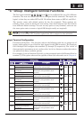
ON Frequency output uses 2nd-stage acceleration
and deceleration values
09 2CH 2-stage Acceleration
and Deceleration
OFF Frequency output uses standard acceleration
and deceleration values
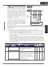
ON Causes output to turn OFF, allowing motor to
free run (coast) to stop
11 FRS Free-run Stop
OFF Output operates normally, so controlled
deceleration stop motor
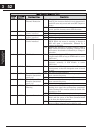
ON When assigned input transitions OFF to ON,
inverter latches trip event and displays E12
12 EXT External Trip
OFF No trip event for ON to OFF, any recorded trip
events remain in history until reset
ON On powerup, the inverter will not resume a Run
command (mostly used in the US)
13 USP Unattended Start
Protection
OFF On powerup, the inverter will resume a Run
command that was active before power loss
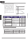
ON The keypad and remote programming devices
are prevented from changing parameters
15 SFT Software Lock
OFF The parameters may be edited and stored
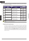
ON16 AT Analog Input
Voltage/Current Select
OFF
Refer to “Analog Input Settings” on page 3-13.
ON The trip condition is reset, the motor output is
turned OFF, and powerup reset is asserted
18 RS Reset Inverter
OFF Normal power-ON operation
351
Configuring Drive
Parameters
3 51
&RQ¿JXULQJ'ULYH
Parameters