


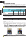
Using the Front Panel Keypad
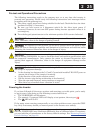
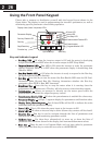
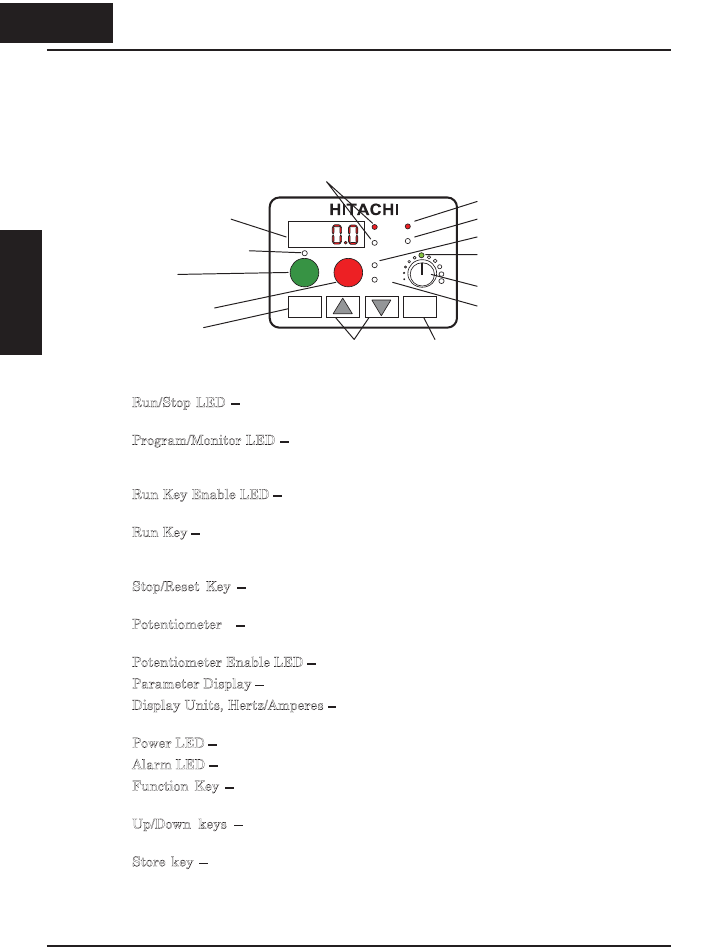
Please take a moment to familiarize yourself with the keypad layout shown in the
figure below. The display is used in programming the inverter’s parameters, as well as
monitoring specific parameter values during operation.
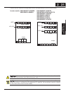
Key and Indicator Legend
x Run/Stop LED – ON when the inverter output is ON and the motor is developing
torque (Run Mode), and OFF when the inverter output is OFF (Stop Mode).
x
P
rogram/Monitor LED – This LED is ON when the inverter is ready for parameter
editing (Program Mode). It is OFF when the parameter display is monitoring data
(Monitor Mode).
x
R
un Key Enable LED – is ON when the inverter is ready to respond to the Run key,
OFF when the Run key is disabled.
x
R
un Key – Press this key to run the motor (the Run Enable LED must be ON first).
Parameter F004, Keypad Run Key Routing, determines whether the Run key
generates a Run FWD or Run REV command.
x
S
top/Reset Key – Press this key to stop the motor when it is running (uses the
programmed deceleration rate). This key will also reset an alarm that has tripped.
x
P
otentiometer – Allows an operator to directly set the motor speed when the
potentiometer is enabled for output frequency control.
x
P
otentiometer Enable LED – ON when the potentiometer is enabled for value entry.
x
P
arameter Display – A 4-digit, 7-segment display for parameters and function codes.
x
D
isplay Units, Hertz/Amperes – One of these LEDs will be ON to indicate the units
associated with the parameter display.
x
P
ower LED – This is ON when the power input to the inverter is ON.
x
A
larm LED – ON when an inverter trip is active (alarm relay contact will be closed).
x
F
unction Key – This key is used to navigate through the lists of parameters and
functions for setting and monitoring parameter values.
x
U
p/Down keys – Use these keys alternatively to move up or down the lists of
parameter and functions shown in the display, and increment/decrement values.
x
S
tore key – When the unit is in Program Mode and you have edited a parameter
value, press the Store key to write the new value to the EEPROM.
226
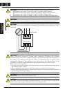
Inverter Mounting
and installation
Display Units (Hertz / Amperes) LEDs
Parameter Display
Run key Enable LED
Run key
Stop/Reset key
PRG
RUN
Hz
RUN
A
2
POWER
A
LARM
STOP
RESET
Function key
Up/Down keys Store key
Power LED
A
larm LED
Run/Stop LED
Program/Monitor LED
Potentiometer Enable LED
Potentiometer
1
FUNC STR
2 26
Inverter Mountingand
installation