


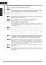
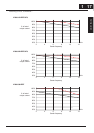
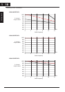
Derating Curves
The maximum available inverter current output is limited by the carrier frequency and
ambient temperature. The carrier frequency is the inverter’s internal power switching
frequency, settable from 2kHz to 12kHz. Choosing a higher carrier frequency tends to
decrease audible noise, but it also increases the internal heating of the inverter, thus
decreasing (derating) the maximum current output capability. Ambient temperature is
the temperature just outside the inverter housingsuch as inside the control cabinet
where the inverter is mounted. A higher ambient temperature decreases (derates) the
inverter’s maximum current output capacity.
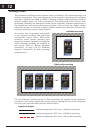
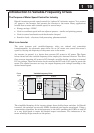
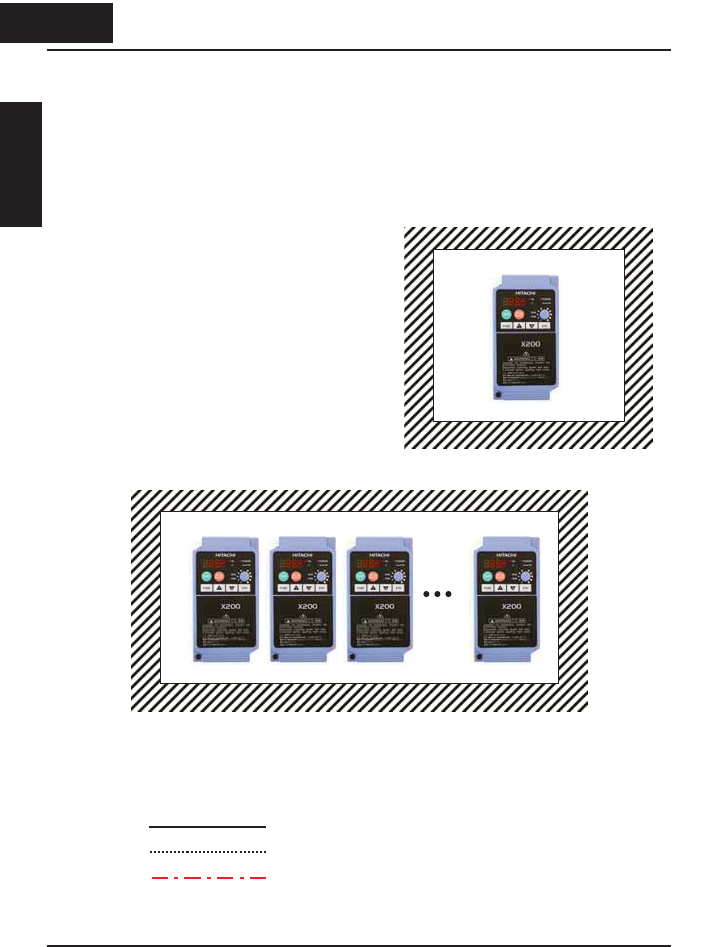
An inverter may be mounted individually
in an enclosure or side-by-side with other
inverter(s)As shown below. Side-by-side
mounting causes greater derating than
mounting inverters separately. Graphs for
either mounting methods are included in
this section. Refer to “Ensure Adequate
Ventilation” on page 2-10 for minimum
clearance dimensions for both mounting
configurations.
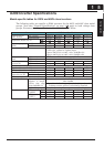
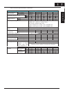
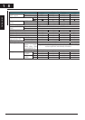
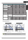
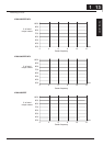
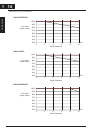
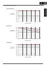
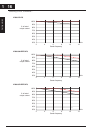
Use the following derating curves to help determine the optimal carrier frequency
setting for your inverter and find the output current derating. Be sure to use the proper
curve for your particular X200 inverter model number.
Legend for Graphs:
Ambient temperature 40qC max., individual mounting
Ambient temperature 50qC max., individual mounting
Ambient temperature 40qC max., side-by-side mounting
112
Enclosure
Individual mounting
Enclosure
Side-by-side mounting
1 12
Getting started