If the Potentiometer Enable LED is OFF, follow these steps below.
Action Display Func./Parameter
(Starting point)
A- - -
“A” Group selected
Press the key. A001 Speed command source setting
Press the key again. 01
00 = Keypad potentiometer
01 = Control terminals
02 = Function F001 setting
03 = ModBus network
04 = Calculate function output
Press the key. 00 00 = Potentiometer (selected)
Press the key. A001
Store parameter, returns to “A”
Group list
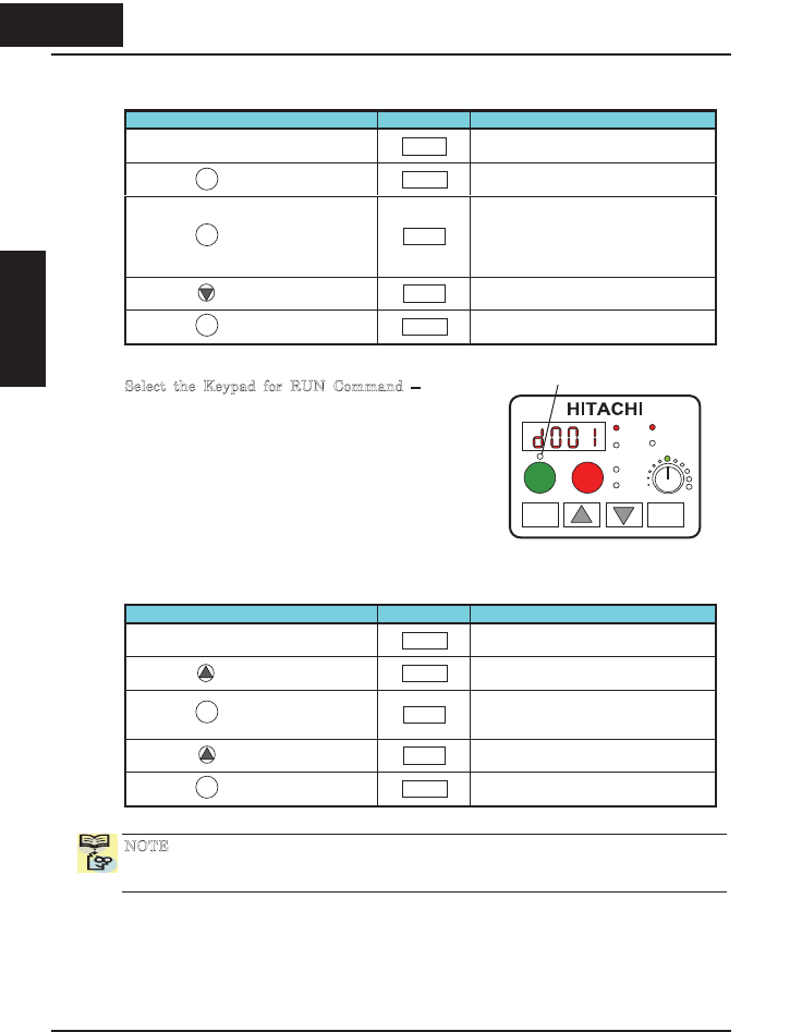
Select the Keypad for RUN Command – To RUN
command causes the inverter to accelerate the motor
to the selected speed. The Run command can arrive
from various sources, including the control terminals,
the Run key on the keypad or the network. In the
figure to the right, notice the Run Key Enable LED,
just above the Run key. If the LED is ON, the Run
key is already selected as the source, and you may
skip this step. Note that the default setting depends
on the country.
If the Potentiometer Enable LED is OFF, follow these steps below (the table resumes
action from the end of the previous table).
Action Display Func./Parameter
(Starting point)
A001
Speed command source setting
Press the key once.
A002
Run command source setting
Press the key.
01
01 = Control terminals
02 = Run key on keypad
03 = ModBus network
Press the key. 02 02 = Run key on keypad (selected)
Press the key.
A002
Store parameter, returns to “A”
Group list
NOTE: After completing the steps above, the Run Key Enable LED will be ON. This
does not mean the motor is trying to run; it means that the RUN key is now enabled.
DO NOT press the RUN key at this time – complete the parameter setup first.
FUNC
2
FUNC
STR
FUNC
STR
1
1
230
Inverter Mounting
and installation
Run Key Enable LED
PRG
RUN
Hz
RUN
A
2
POWER
A
LARM
STOP
RESET
1
FUNC STR
2 30
Inverter Mountingand
installation


