


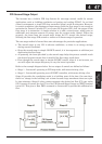
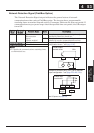
Analog Input Disconnect Detect
This feature is useful when the inverter receives a speed reference from an external
device. Upon input signal loss at either the [O] or [OI] terminal, the inverter normally
just decelerates the motor to a stop. However, the inverter can use the intelligent output
terminal [Dc] to signal other devices that a signal loss has occurred.
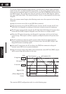
V
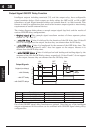
oltage signalloss at [O]terminal - Parameter B082 is the Start Frequency Adjustment.
It sets the beginning (minimum) output frequency when the speed reference source is
greater than zero. If the analog input at terminal [O] is less than the Start Frequency,
the inverter turns ON the [Dc] output to indicate a signal loss condition.
C
urrent signal loss at [OI] terminal - The [OI] terminal accepts a 4mA to 20mA signal,
with 4mA representing the beginning of the input range. If the input current falls below
4mA, the inverter applies a threshold to detect signal loss.
Note that a signal loss is not an inverter trip event. When the analog input value is again above
the B082 value, the [Dc] output turns OFF. There is no error condition to clear.
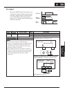
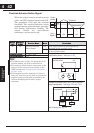
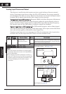
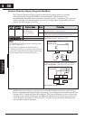
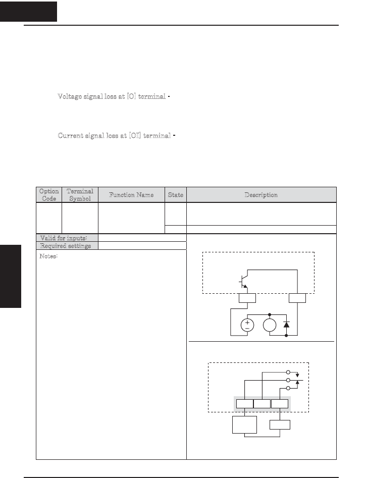
Option
Code
Terminal
Symbol
Function Name State Description
ON when the [O] input value < B082 Start Frequency
Adjustment (signal loss detected), or when the [OI
input current is less than 4mA
06 Dc Analog Input
Disconnect Detect
OFF when no signal loss is detected
Valid for inputs: 11, AL0 – AL2
Required settings A001=01, B082
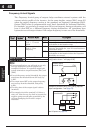
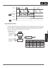
Notes:
x The [Dc] output can indicate an analog signal
disconnect when the inverter is in Stop Mode, as
well as Run Mode.
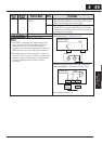
x The example circuit for terminal [11] drives a
relay coil. Note the use of a diode to prevent the
negative-going turn-off spike generated by the
coil from damaging the inverter’s output
transistor.
Example for terminal [11] (default output
configuration shown – see page 3-54):
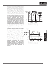
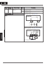
Example for terminal [AL0], [AL1], [AL2] (requires
output configuration – see page 4-35 and 3-54):
See I/O specs on page 4-6
446
Operations and
Monitoring
RY
Inverter output
terminal circuit
CM2 11
Dc
AL1
Power
supply
Load
AL0 AL2
Inverter logic
circuit board
Dc
4 46
Operations and
Monitoring