


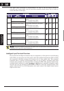
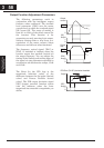
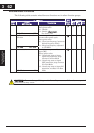
Output Function Adjustment Parameters
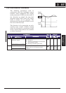
The following parameters work in
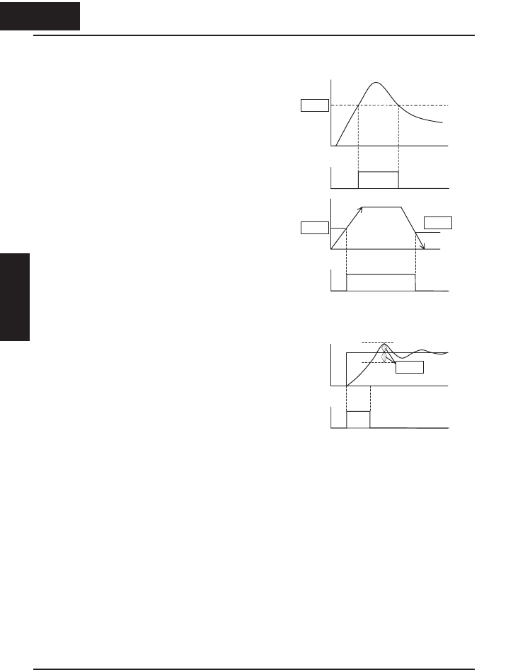
conjunction with the intelligent output
function, when configured. The overload
level parameter (C041) sets the motor
current level at which the overload signal
[OL] turns ON. The range of setting is
from 0% to 200% of the rated current for
the inverter. This function is for
generating an early warning logic output,
without causing either a trip event or a
restriction of the motor current (those
effects are available on other functions).
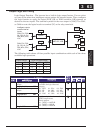
The frequency arrival signal, [FA1] or
[FA2], is intended to indicate when the
inverter output has reached (arrived at)
the target frequency. You can adjust the
timing of the leading and trailing edges of
the signal via two parameters specified to
acceleration ad deceleration ramps, C042
and C043.
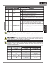
The Error for the PID loop is the
magnitude (absolute value) of the
difference between the Set point (desired
value) and Process Variable (actual
value). The PID output deviation signal
[OD] (output terminal function option
code 04) indicates when the error
magnitude has exceeded a magnitude you
define.
Output
fre
q
.
C042
C043
[FA2]
output
1
0
t
t
C041
Output
current
[OL]
output
0
1
0
t
t
t
C044
[OD]
output
1
0
t
Output
PID Error (PV-SP) deviation threshold
358
Configuring Drive
Parameters
3 58
&RQ¿JXULQJ'ULYH
Parameters