


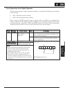
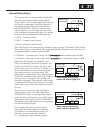
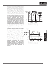
Internal Relay Output
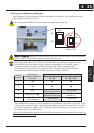
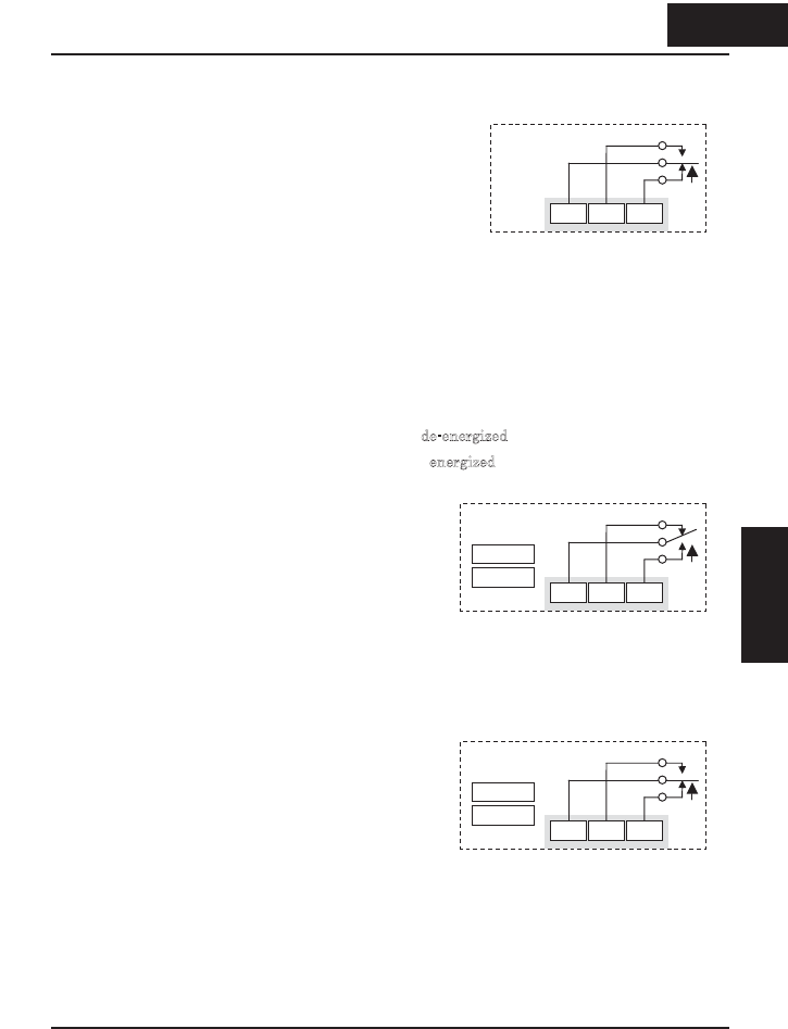
The inverter has an internal relay output with
normally open and normally closed contacts
(Type 1 form C). The output signal that controls
the relay is configurable; the Alarm Signal is
the default setting. Thus, the terminals are
labeled [AL0], [AL1], [AL2], as shown to the
right. However, you can assign any one of the
nine intelligent outputs to the relay. For wiring
purposes, the general terminal functions are:
x [AL0] – Common contact
x [AL1] – Normally open contact
x [AL2] – Normally closed contact
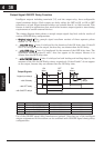
The relay itself can be configured as “normally open or closed.” Parameter C036, Alarm
Relay Active State, is the setting. This setting determines whether or not the relay coil
is energized when its output signal is OFF:
x C036=00 – “Normally open” (relay coil is d
e-energized when output signal is OFF)
x C036=01 – “Normally closed” (relay coil is e
nergized when the output signal is OFF)
Since the relay already has normally open
[AL1] and normally closed [AL2] contacts, the
purpose of the ability to invert the relay coil’s
active state may not be obvious.
It allows you to
determine whether or not an inverter power
loss causes the relay to change state.
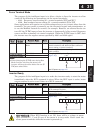
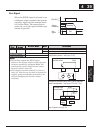
The
default relay configuration is the Alarm Signal
(C026=05), as shown to the right. And, C036=01
sets the relay to “normally closed” (relay coil
normally energized). The reason for this is that
a typical system design will require an inverter
power loss to assert an alarm signal to external
devices.
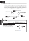
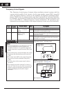
The relay can be used for other intelligent
output signals, such as the Run Signal (set
C026=00). For these remaining output signal
types, the relay coil typically must NOT change
state upon inverter power loss (set C036=00).
The figure to the right shows the relay settings
for the Run Signal output.
If you assign the relay an output signal
other than the Alarm Signal, the inverter
can still have an Alarm Signal output. In
this case, you can assign it to terminal
[11] , providing an open collector output.
AL1AL0 AL2
Inverter logic
circuit board
AL1AL0 AL2
Inverter logic
circuit board
C026=00
C036=00
Relay shown with inverter
p
ower ON, Run Si
g
nal OF
F
RUN
AL1AL0 AL2
Inverter logic
circuit board
C026=05
C036=01
Relay shown with inverter
p
ower ON, Alarm Si
g
nal OF
F
AL
437
Operations and
Monitoring
4 37
Operations and
Monitoring