


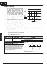
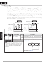

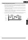
Analog Input Current/Voltage Select
The [AT] terminal selects whether the inverter uses the voltage [O] or current [OI]
input terminals for external frequency control. When intelligent input [AT] is ON, you
can set the output frequency by applying a current input signal at [OI]-[L]. When the
[AT] input is OFF, you can apply a voltage input signal at [O]-[L] to set the output
frequency. Note that you must also set parameter A001 = 01 to enable the analog
terminal set for controlling the inverter frequency.
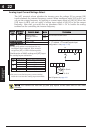
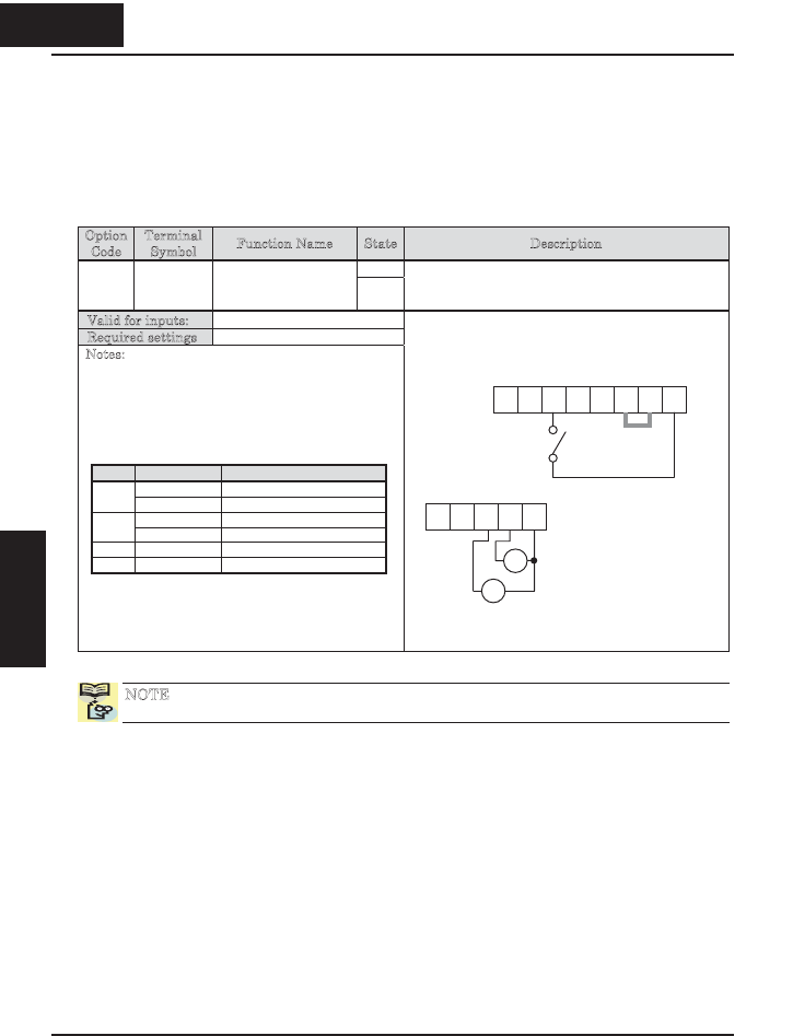
Option
Code
Terminal
Symbol
Function Name State Description
ON16 AT Analog Input
Voltage/Current
Select
OFF
See the table down below
Valid for inputs: C001~C005
Required settings A001 = 01
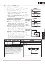
Notes:
x If the [AT] option is not assigned to any
intelligent input terminal, then inverter
recognizes [AT] = OFF in following table.
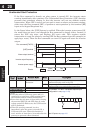
Combination of A005 setting and [AT] input
for analog input activation.
x Be sure to set the frequency source setting
A001=01 to select the analog input terminals.
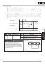
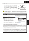
Example (default input configuration shown
for –FU models; –FE models require input
configuration—see page 3–49):
See I/O specs on page 4–6.
NOTE: You cannot use both the [O] and [OI] inputs at the same time on the X200
inverter.
5 4 3 2 1 L
PCS
P24
AT
AM H O OI L
Å
+ -
4-20 mA
0-10 V
422
Operations and
Monitoring
A005 [AT] Input Analog Input Configuration
ON Keypad Pot
02
OFF [O]
ON Keypad Pot
03
OFF [OI]
04 (ignored)[O]
05 (ignored)[OI]
4 22
Operations and
Monitoring