


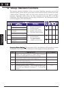
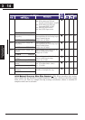
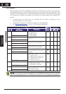
DC Braking (DB) Settings
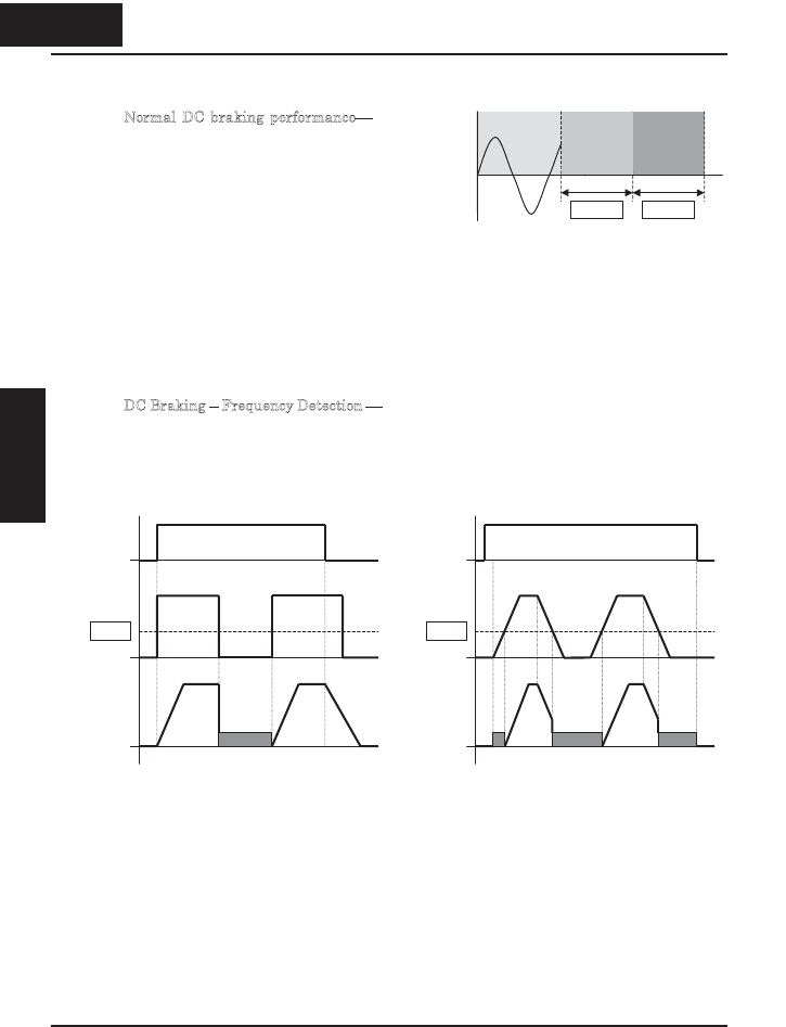
Normal DC braking performance The DC
braking feature can provide additional
stopping torque when compared to a normal
deceleration to a stop. DC braking is
particularly useful at low speeds when
normal deceleration torque is minimal.
When you set A051 to 01 (Enable during
stop), and the RUN command (FW/RV
signal) turns OFF, the inverter injects a DC
voltage into the motor windings during
deceleration below a frequency you can
specify (A052).
The braking power (A054) and duration (A055) can both be set. You can optionally
specify a wait time before DC braking (A053), during which the motor will free run.
D
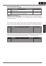
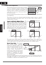
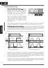
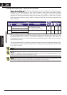
C Braking – Frequency Detection You can instead set DC braking to operate during
RUN mode only, by setting A051 to 02 (Frequency detection). In this case DC braking
operates when the output frequency comes down to the one you specified in A052 while
the RUN command is still active. Refer to the graphs figures below.
External DB and Internal DC braking are invalid during the frequency detection mode.
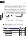
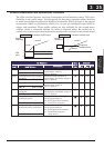
Example 1, (above left) shows the performance with A051=02 with a step-changing
frequency reference. In this case, when the reference goes to 0, the inverter immediately
starts DC braking because the set point drops below the value specified in A052. DC
braking continues until the set point exceeds A052. There will be no DC braking at next
downward transition because the FW input is OFF.
Example 2, (above right) shows a gradually changing frequency reference, for example
by analog input. In this case, there will be a DC braking period at starting because the
frequency set point is lower than the value specified in A052.
Running DC brakeFree run
+
0
-
t
A053 A055
FW
ON
F-SET
A052
DB
Ex.1) Step change in F-SET.
F-OUT
FW
ON
F-SET
A052
Ex.2) Analog change in F-SET.
F-OUT
DB DB DB
318
Configuring Drive
Parameters
3 18
&RQ¿JXULQJ'ULYH
Parameters