


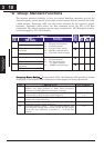
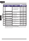
“A” Function Defaults
Func.
Code
Name /
SRW Display
Description
Run
Mode
Edit
-FE
(EU)
-FU
(USA)
Units
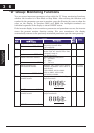
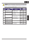
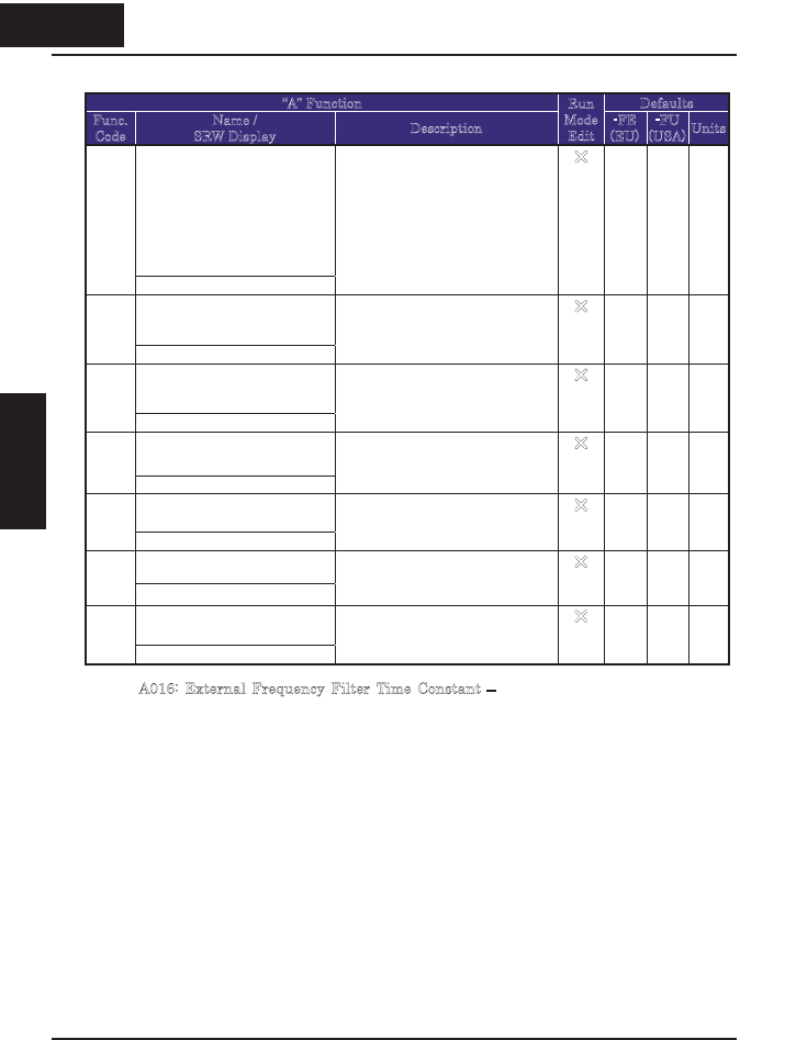
[AT] selectionA005
AT-Slct O/VR
Five options; select codes:
02...Select between [O] and
keypad potentiometer at [AT]
03...Select between [OI] and
integrated POT at [AT]
04...Only [O] input active
05...Only [OI] input active
U
02 02
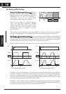
O-L input active range start
frequency
A011
O-EXS 0000.0Hz
The output frequency
corresponding to the analog input
range starting point,
range is 0.0 to 400.0
U
0.0 0.0 Hz
O-L input active range end
frequency
A012
O-EXE 0000.0Hz
The output frequency
corresponding to the analog input
range ending point,
range is 0.0 to 400.0
U
0.0 0.0 Hz
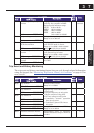
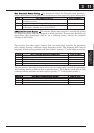
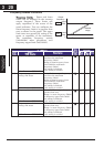
O-L input active range start
voltage
A013
O-EX%S 00000%
The starting point (offset) for the
active analog input range,
range is 0. to 100.
U
0. 0. %
O-L input active range end
voltage
A014
O-EX%E 00000%
The ending point (offset) for the
active analog input range,
range is 0. to 100.
U
100. 100. %
O-L input start frequency
enable
A015
O-LVL 0Hz
Two options; select codes:
00}Use offset (A011 value)
01}Use 0Hz
U
01 01
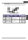
External frequency filter time
constant
A016
F-SAMP 00008
Range n = 1 to 17, where n =
number of samples for avg.
U
8. 8. Sam-
ples
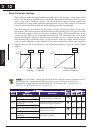
A016: External Frequency Filter Time Constant – This filter smoothes the analog
input signal for the inverter’s output frequency reference. A016 set the filter range
from n=1 to 16. This is a simple moving average calculation, where n (number of
samples used) can be selected.
314
Configuring Drive
Parameters
3 14
&RQ¿JXULQJ'ULYH
Parameters