


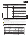
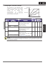
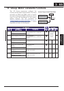

Analog Signal Calibration Settings
The functions in the following table
configure the signals for the analog
input terminals. Note that these
settings do not change the
current/voltage or sink/source
characteristics – only the zero and
span (scaling) of the signals.
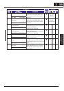
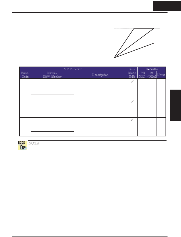
“C” Function Defaults
Func.
Code
Name /
SRW Display
Description
Run
Mode
Edit
-FE
(EU)
-FU
(USA)
Units
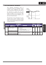
O input span calibrationC081
O-ADJ 0100.0%
Scale factor between the external
frequency command on terminals
L–O (voltage input) and the
frequency output,
range is 0.0 to 200%
9
100.0 100.0 %
OI input span calibrationC082
OI-ADJ 0100.0%
Scale factor between the external
frequency command on terminals
L–OI (voltage input) and the
frequency output,
range is 0.0 to 200%
9
100.0 100.0 %
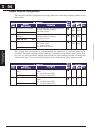
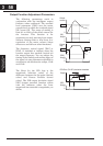
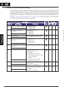
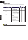
AM offset calibrationC086
AM OFFST 0000.0V
Offset adjustment of AM output.
Range is 0.0 to 10.0
Adjust together with B080 (AM
gain adjustment)
- See page 3-40, 4-55 for details.
9
0.0 0.0 V
NOTE: When you restore factory default settings, the values will change to those listed
above. Be sure to manually reconfigure the values for your application, if needed, after
restoring factory defaults.
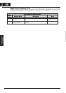
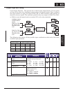
Max. freq
Max. freq /2
10V, 20mA5V, 12mA
200%
100%
50%
0
0V, 4mA
Freq setpoint
361
Configuring Drive
Parameters
3 61
&RQ¿JXULQJ'ULYH
Parameters