


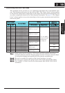
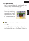
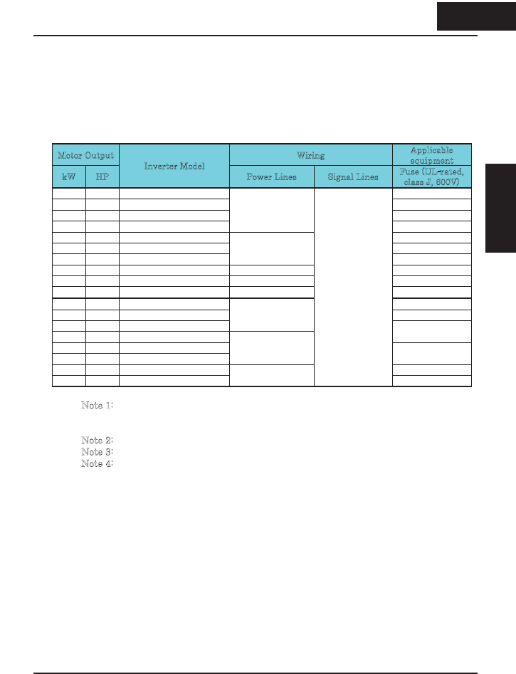
Determining Wire and Fuse Sizes
The maximum motor currents in your application determines the recommended wore
size. The following table gives the wire size in AWG. The “Power Lines” column applies
to the inverter input power, output wires to the motor, the earth ground connection, and
any other components shown in the “Basic System Description” on page 2-7. The “Signal
Lines” column applies to any wire connecting to the two green connectors just inside the
front cover panel.
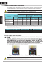
Motor Output Wiring
Applicable
equipment
kW HP
Inverter Model
Power Lines Signal Lines
Fuse (UL-rated,
class J, 600V)
0.2 1/4 X200-002SFEF/NFU 10A
0.4 1/2 X200-004SFEF/NFU 10A
0.55 3/4 X200-005SFEF 10A
0.75 1 X200-007SFEF/NFU
AWG14 / 2.1mm
2
15A
1.1 1 1/2 X200-011SFEF 15A
1.5 2 X200-015SFEF/NFU 20A
2.2 3 X200-022SFEF/NFU
AWG10 / 5.3mm
2
30A
3.7 5 X200-037LFU AWG12 / 3.3mm
2
30A
5.5 7 1/2 X200-055LFU AWG10 / 5.3mm
2
40A
7.5 10 X200-075LFU AWG8 / 8.4mm
2
50A
0.4 1/2 X200-004HFEF/HFU 3A
0.75 1 X200-007HFEF/HFU 6A
1.5 2 X200-015HFEF/HFU
AWG16 / 1.3mm
2
2.2 3 X200-022HFEF/HFU
10A
3.0 4 X200-030HFEF
4.0 5 X200-040HFEF/HFU
AWG14 / 2.1mm
2
(60qC only)
15A
5.5 7 1/2 X200-055HFEF/HFU 20A
7.5 10 X200-075HFEF/HFU
AWG12 / 3.3mm
2
(60qC only)
18 to 28 AWG /
0.14 to 0.75 mm
2
shielded wire
(see Note 4)
25A
Note 1: Field wiring must be made by a UL-Listed and CSA-certified closed-loop
terminal connector sized for the wire gauge involved. Connector must be fixed
by using the crimping tool specified by the connector manufacturer.
N
ote 2: Be sure to consider the capacity of the circuit breaker to be used.
N
ote 3: Be sure to use a larger wire gauge if power line length exceeds 66ft. (20m).
N
ote 4: Use 18 AWG / 0.75mm
2
wire for the alarm signal wire ([AL0], [AL1], [AL2]
terminals).
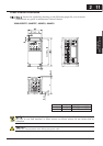
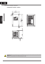
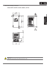
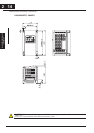
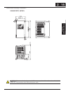
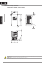
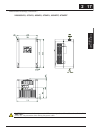
Inverter Mounting
and installation
219
2 19
Inverter Mountingand
installation