


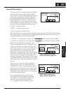
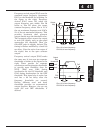
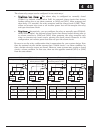
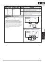
The alarm relay output can be configured in two main ways:
x
T
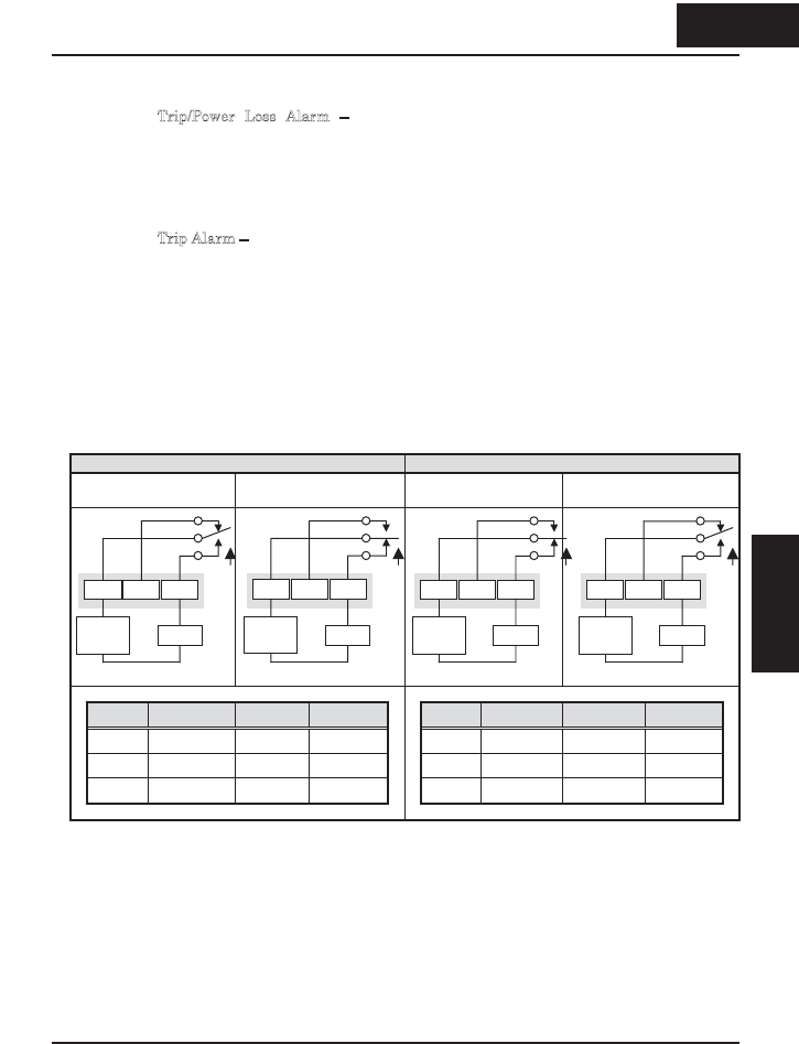
rip/Power Loss Alarm – The alarm relay is configured as normally closed
(C036=1) by default, shown below (left). An external alarm circuit that detects
broken wiring also as an alarm connects to [AL0] and [AL1]. After powerup and
short delay (< 2 seconds), the relay energizes and the alarm circuit is OFF. Then,
either an inverter trip event or an inverter power loss will de-energize the relay
and open the alarm circuit
x
T
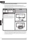
rip Alarm – Alternatively, you can configure the relay as normally open (C036=0),
shown below (right). An external alarm circuit that detects broken wiring also as
an alarm connects to [AL0] and [AL2]. After powerup, the relay energizes only
when an inverter trip event occurs, opening the alarm circuit. However, in this
configuration, an inverter power loss does not open the alarm circuit.
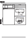
Be sure to use the relay configuration that is appropriate for your system design. Note
that the external circuits shown assume that a closed circuit = no alarm condition (so
that a broken wire also causes an alarm). However, some systems may require a closed
circuit = alarm condition. In that case, then use the opposite terminal [AL1] or [AL2]
from the ones shown.
N.C. contacts (C036=01) N.O. contacts (C036=00)
During normal operation When an alarm occurs or
when power is OFF
During normal operation
or when power is OFF
When an alarm occurs
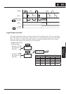
Power Run Mode AL0-AL1 AL0-AL2 Power Run Mode AL0-AL1 AL0-AL2
ON Normal Closed Open ON Normal Open Closed
ON Trip Open Closed ON Trip Closed Open
OFF – Open Closed OFF – Open Closed
AL1
Power
supply
Load
AL0 AL2
AL1
Power
supply
Load
AL0 AL2
AL1
Power
supply
Load
AL0 AL2
AL1
Power
supply
Load
AL0 AL2
445
Operations and
Monitoring
4 45
Operations and
Monitoring