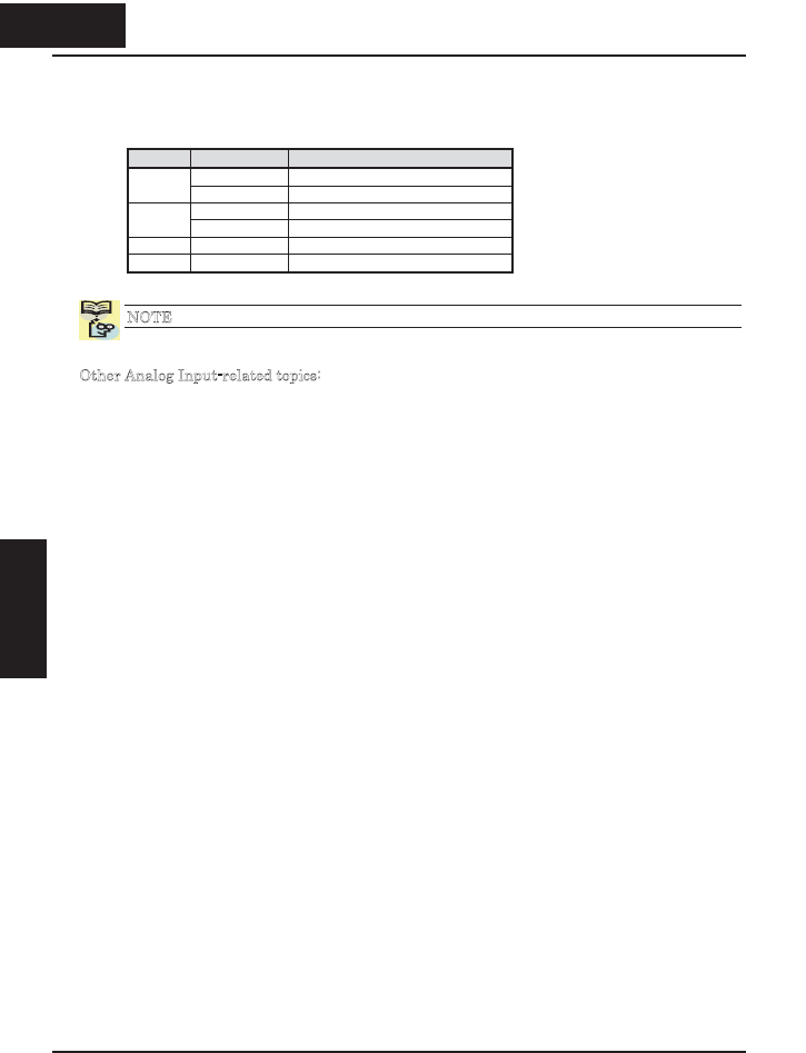
The following table shows the available analog input settings. Parameter A005 and the
input terminal [AT] determine the External Frequency Command input terminals that
are available, and how they function. The analog inputs [O] and [OI] use terminal [L] as
the reference (signal return).
A005 [AT] Input Analog Input Configuration
ON Keypad Pot
02
OFF [O]
ON Keypad Pot
03
OFF [OI]
04 (ignored) [O]
05 (ignored) [OI]
NOTE: You cannot use [O] and [OI] inputs simultaneously on the X200 series inverter.
Other Analog Input-related topics:
x “Analog Input Settings” on page 3–13
x “Additional Analog Input Settings” on page 3–28
x “Analog Signal Calibration Settings” on page 3–61
x “Analog Input Current/Voltage Select” on page 4–22
x “ADD Frequency Enable” on page 4–30
x “Analog Input Disconnect Detect” on page 4–46
456
Inverter Mounting
and installation
4 56
Operations and
Monitoring


