


Monitoring Parameters with the Display
After using the keypad for parameter editing, it’s a
good idea to switch the inverter from Program Mode to
Monitor Mode. The PRG LED will be OFF, and the
Hertz or Ampere LED indicates the display units.
For the powerup test, monitor the motor speed
indirectly by viewing the inverter’s output frequency.
The
output frequency
must not be confused with
base
frequency
(50/60 Hz) of the motor, or the
carrier
frequency
(switching frequency of the inverter, in the kHz range). The monitoring
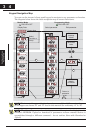
functions are in the “D” list, located near the top left of the “Keypad Navigation Map”on
page 2-26.
O
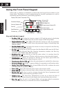
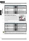
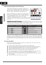
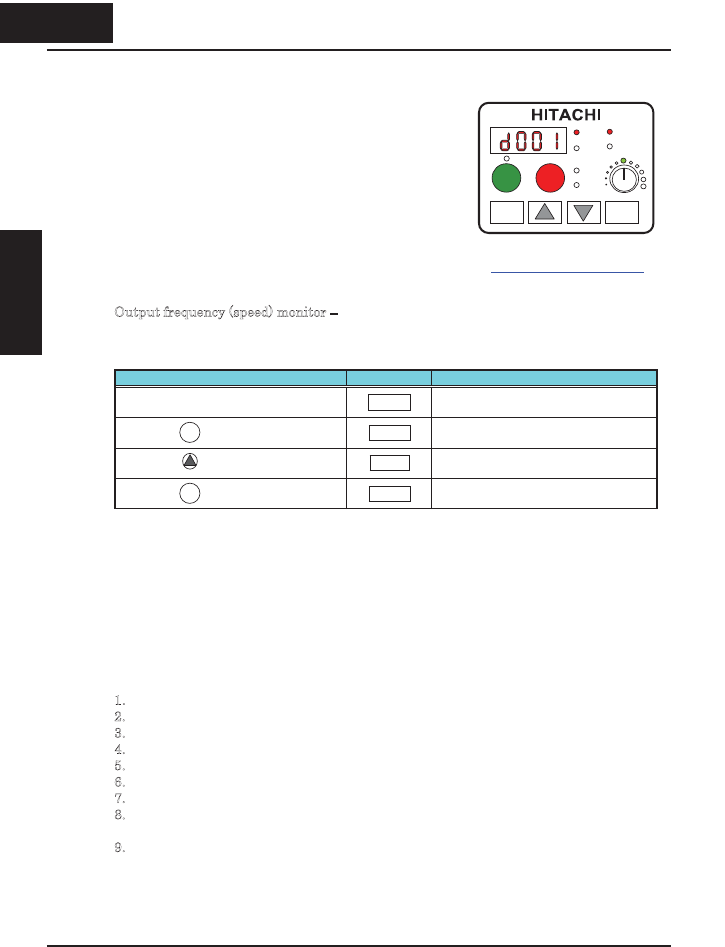
utput frequency(speed) monitor – Resuming keypad operation from the previous table,
follow the steps below. Or instead, you can simply power cycle the inverter, which
automatically sets the display to D001 (output frequency value).
Action Display Func./Parameter
(Starting point)
H004
Motor poles parameter
Press the key.
H- - -
“H” Group selected
Press the key.
d001
Output frequency selected
Press the key. 0.0 Output frequency displayed
When the inverter displays a monitor value, the PRG LED is OFF. This confirms the
inverter is not in programming mode, even while you are selecting the particular
monitoring parameter. The display shows the current speed (is zero at this point). The
Hz LED will be ON, indicating the display units. For current, the Amperes LED will be
ON.
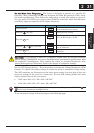
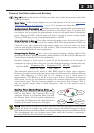
Running the Motor
If you have programmed all the parameters up to this point, you’re ready to run the
motor! First, review this checklist:
1
. Verify the power LED is ON. If not, check the power connections.
2
. Verify the Potentiometer Enable LED is ON. If it is OFF, check the A001 setting.
3
. Verify the Run Key Enable LED is ON. If it is OFF, check the A002 setting.
4
. Verify the PRG LED is OFF. If it is ON, review the instructions above.
5
. Make sure the motor is disconnected from any mechanical load.
6
. Turn the potentiometer to the minimum position (completely counter clock-wise).
7
. Now, press the RUN key on the keypad. The RUN LED will turn ON.
8
. Slowly increase the potentiometer setting in clockwise fashion. The motor should
start turning.
9
. Press the STOP key to stop the motor rotation.
1
FUNC
FUNC
234
Inverter Mounting
and installation
PRG
RUN
Hz
RUN
A
2
POWER
A
LARM
STOP
RESET
1
FUNC STR
2 34
Inverter Mountingand
installation