


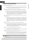
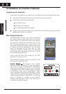
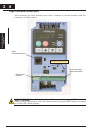
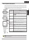
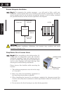
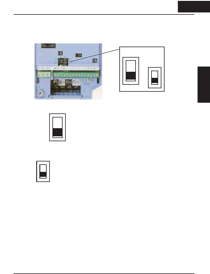
DIP Switch Introduction
The inverter has internal DIP switches, located near the middle of the logic connectors
as shown below. This section provides an introduction. Refer to later chapters that
discuss the DIP switch operation in more detail.
The 485/OPE (RS485/Operator) DIP switch configures the
inverter’s RJ45 serial port. You can use either the inverter’s
integrated keypad or the OPE-SRmini connected via a cable to
the serial port. In this case, SW7 should be set OPE (default
setting). The port is configured for RS422 in this setting.
Inverter control via a ModBus network communication requires
the “485” setting. See “Connecting the Inverter to ModBus” on
page B-3 for more details.
DIP switch SW8 controls the Emergency stop signal input.
Turning this DIP switch ON will enable the inverter to receive a
Emergency stop signal from the dedicated safe stop terminal
(#3). The inverter will shut off its output by means of direct
hardware control (bypassing the internal microprocessor normal
program execution) when a signal is given to this terminal.
Additionally, the intelligent input terminal assignment will be
changed automatically when SW8 is ON. See “Safe Stop” on
page 4-32 for more details.
25
Inverter Mounting
and installation
SW7
SW8
485
OPE
ON
OFF
SW7
485
OPE
SW8
ON
OFF
2 5
Inverter Mountingand
installation