


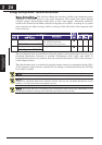
Additional Analog Input Settings
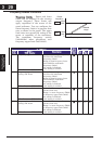
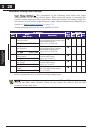
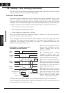
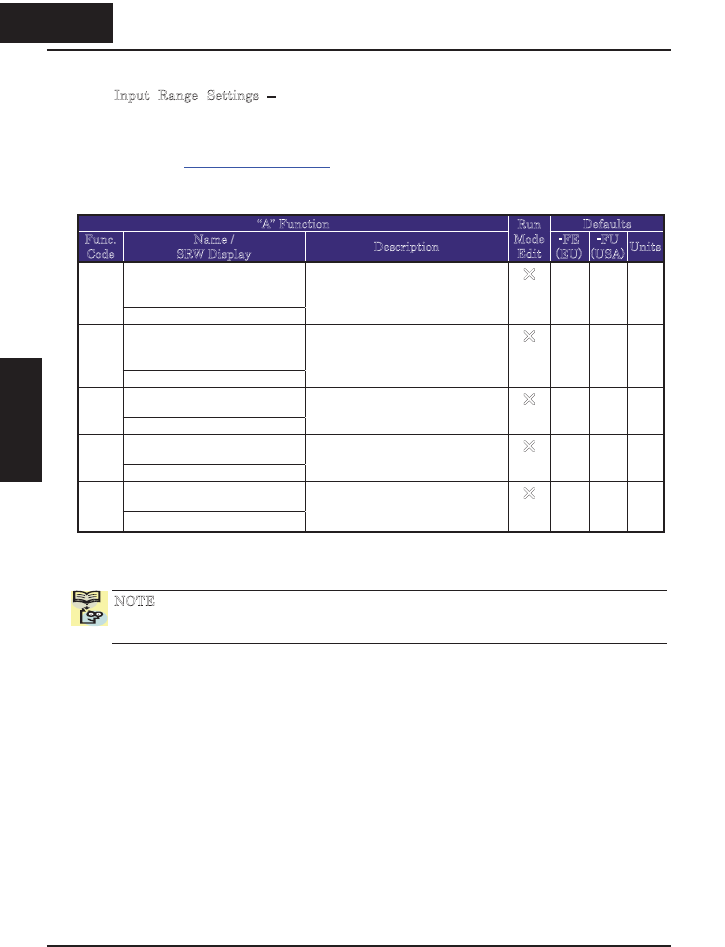
Input Range Settings – The parameters in the following table adjust the input
characteristics of the analog current input. When using the inputs to command the
inverter output frequency, these parameters adjust the starting and ending ranges for
the current, as well as the output frequency range. Related characteristic diagrams are
located in “
Analog Input Settings” on page 3-13.
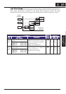
Analog sampling setting is the value specified in A016.
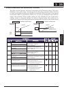
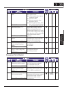
“A” Function Defaults
Func.
Code
Name /
SRW Display
Description
Run
Mode
Edit
-FE
(EU)
-FU
(USA)
Units
[OI]-[L] input active range
start frequency
A101
OI-EXS 0000.0Hz
The output frequency
corresponding to the analog input
range starting point,
range is 0.0 to 400.0 Hz
U
0.0 0.0 Hz
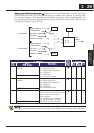
[OI]-[L] input active range
end frequency
A102
OI-EXE 0000.0Hz
The output frequency
corresponding to the current
input range ending point,
range is 0.0 to 400.0 Hz
U
0.0 0.0 Hz
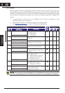
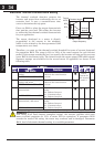
[OI]-[L] input active range
start current
A103
OI-EX%S 00000%
The starting point (offset) for the
current input range,
range is 0. to 100.%
U
0. 0. %
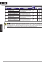
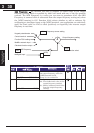
[OI]-[L] input active range
end voltage
A104
OI-EX%E 00000%
The ending point (offset) for the
current input range,
range is 0. to 100.%
U
100. 100. %
[OI]-[L] input start frequency
enable
A105
OI-LVL 0Hz
Two options; select codes:
00}Use offset (A101 value)
01}Use 0Hz
U
01 01
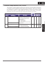
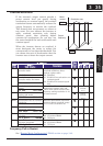
Refer to parameter A011 to A015 for analog voltage input.
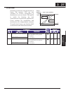
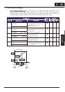
N
OTE: You cannot use voltage input and current input ([O] and [OI] input) at the same
time on the X200 series inverter. Please do not connect the cable to [O] and [OI]
terminals at the same time.
328
Configuring Drive
Parameters
3 28
&RQ¿JXULQJ'ULYH
Parameters