


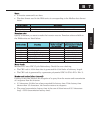

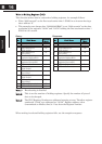
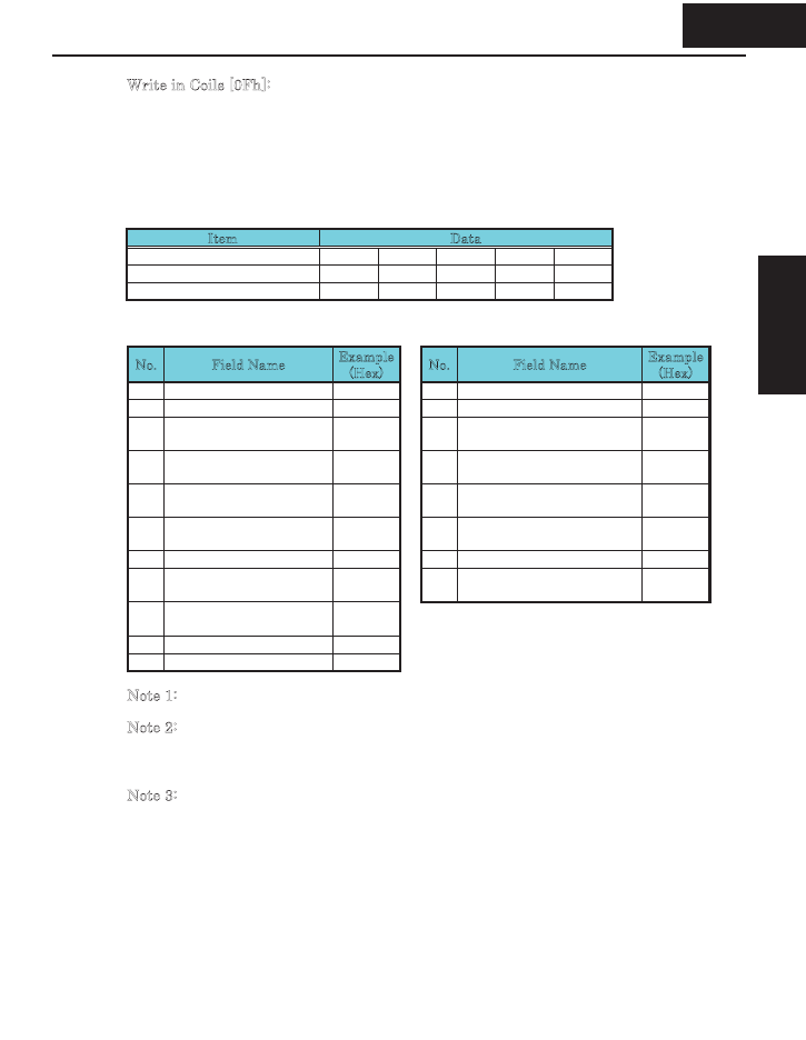
Write in Coils [0Fh]:
This function writes data in consecutive coils. An example follows:
x Change the state of intelligent input terminal [1] to [5] of an inverter having a slave
address “8.”
x This example assumes the intelligent input terminals have terminal states listed
below.
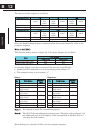
Item Data
Intelligent input terminal [1] [2] [3] [4] [5]
Coil Number 7 8 9 10 11
Terminal status ON ON ON OFF ON
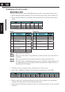
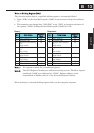
Query: Response:
No. Field Name
Example
(Hex)
No. Field Name
Example
(Hex)
1 Slave address *1 08 1 Slave address 08
2 Function code 0F 2 Function code 0F
3 Coil start address *3
(high order)
00 3 Coil start address *3
(high order)
00
4 Coil start address *3
(low order)
06 4 Coil start address *3
(low order)
06
5 Number of coils
(high order)
00 5 Number of coils
(high order)
00
6 Number of coils
(low order)
05 6 Number of coils
(low order)
05
7 Byte number *2 02 7 CRC-16 (high order) 75
8 Change data
(high order)
17 8 CRC-16 (low order) 50
9 Change data
(low order)
00
10 CRC-16 (high order) 83
11 CRC-16 (low order) EA
Note 1: Broadcasting is disabled.
N
ote 2: The change data is a set of high-order data and low-order data. So when the
size (in bytes) of data to be changed is an odd start coil number (“7”), add “1”
to the data size (in bytes) to make it an even number.
N
ote 3: The PDU Coils are addressed starting at zero. Therefore coils numbered 1-31
are addressed as 0-30. Coil address value (transmitted on Modbus line) is 1
less than the Coil Number.
B15
Appendix B
B 15
Appendix B