


Read this entire installation section
before you start installation.
SAFETY PRECAUTIONS
ELECTRIC SHOCK can kill.
• Only qualified personnel should
perform this installation.
•
Turn the input power OFF at the
disconnect switch or fuse box
before working on this equipment.
• Turn the Power Switch on the DC-655 “OFF” before
connecting or disconnecting output cables, wire
feeder or remote connections, or other equipment.
• Do not touch electrically hot parts.
• Always connect the Idealarc DC-655 grounding ter-
minal (located on the welder near the reconnect
panel) to a good electrical earth ground.
SELECT SUITABLE LOCATION
Place the welder where clean cooling air can freely cir-
culate in through the front louvers and out through the
rear louvers. Dirt, dust or any foreign material that can
be drawn into the welder should be kept at a mini-
mum. Failure to observe these precautions can result
in excessive operating temperatures and nuisance
shut-downs.
STACKING
The DC-655 may be stacked three-high provided the
bottom machine is on a stable, hard, level surface. Be
sure that the two pins in the roof fit into the slots in the
base of the DC-655 above it.
TILTING
Do not place the machine on a surface that is inclined
enough to create a risk of the machine falling over.
ELECTRICAL
INPUT CONNECTIONS
Before installing the machine check that the input sup-
ply voltage, phase, and frequency are the same as the
voltage, phase, and frequency as specified on the
welder nameplate.
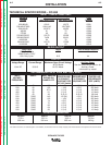
Use input wire sizes that meet local electrical codes or
see the Technical Specifications page in this manual.
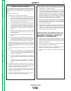
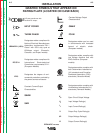
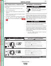
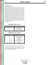
Input power supply entry is through the hole in the
Case Back Assembly. See Figure A.1 for the location
of the machine’s input cable entry opening, Input
Contactor (CR1), and reconnect panel.
FUSE AND WIRE SIZES
Protect the input circuit with the super lag fuses or
delay type circuit breakers listed on the Technical
Specifications page of this manual for the machine
being used. They are also called inverse time or ther-
mal/magnetic circuit breakers.
DO NOT use fuses or circuit breakers with a lower amp
rating than recommended. This can result in “nui-
sance” tripping caused by inrush current even when
machine is not being used for welding at high output
currents.
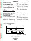
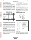
GROUND CONNECTION
Ground the frame of the machine. A ground
terminal marked with the symbol is located inside
the case back of the machine near the input contactor.
Access to the input box assembly is at the upper rear
of the machine. See your local and national electrical
codes for proper grounding methods. Use grounding
wire sizes that meet local electrical codes or see the
Technical Specifications page in this manual.
INSTALLATION
A-4 A-4
IDEALARC DC-655
Return to Section TOC Return to Section TOC Return to Section TOC Return to Section TOC
Return to Master TOC Return to Master TOC Return to Master TOC Return to Master TOC
WARNING
INPUT POWER SUPPLY
CABLE WITH BUSHING
OR BOX CONNECTOR
INPUT
CONTACTOR (CR1)
RECONNECT
PANEL ASSEMBLY
FIGURE A.1 - ELECTRICAL INPUT CONNECTIONS