


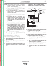
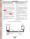

6. Connect NA-5/-5R wire feeder control jumpers on
Voltage Control Board. See NA-5/-5R Operator’s
Manual.
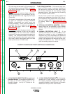
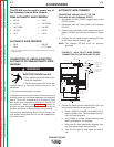
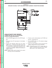
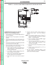
NOTE: The connection diagram shown in Figure C.2
shows the electrode connected for positive
polarity. To change polarity:
a. Set the Idealarc DC-655 POWER toggle
switch to the OFF (0) position.
b. Move the electrode cable to the negative (-)
output terminal. (High inductance or low
inductance as needed).
c. Move the work cable to the positive (+) output
terminal.
d. If connecting lead #21 to the terminal strip,
connect it to the +21 terminal (to match work
polarity). If work polarity changes back to
negative, lead #21 must be connected to the -
21 terminal.
NOTE: For proper NA-5 operation, the electrode
cables must be secured under the clamp bar
on the left side of the NA-5 Control Box.
7. Set the DC-655 OUTPUT CONTROL switch to the
“Remote” position and the OUTPUT TERMINALS
switch to the “Remote” position.
ACCESSORIES
C-5 C-5
IDEALARC DC-655
Return to Section TOC Return to Section TOC Return to Section TOC Return to Section TOC
Return to Master TOC Return to Master TOC Return to Master TOC Return to Master TOC