


Return to Section TOC Return to Section TOC Return to Section TOC Return to Section TOC
Return to Master TOC Return to Master TOC Return to Master TOC Return to Master TOC
TROUBLESHOOTING & REPAIR
F-19 F-19
IDEALARC DC-655
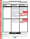
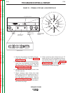
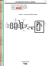
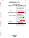
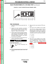
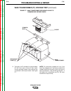
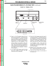
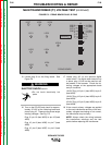
FIRING BOARD TEST (continued)
IF THEN
LED 7 is ON 32 VAC power is being supplied to the
firing board from leads #203 and
#204 connected to the phase angle
winding in the Main Transformer.
Normal is 32 VAC.
LED 7 is not lit or is dimmer than The proper AC voltage may not be
the other LEDs reaching the firing board. Check for
loose or faulty connections. Perform
the Main Transformer Test.
LED 8 is ON 32 VAC power is being supplied to the
firing board from leads #205 and #206
connected to the phase angle winding in
the Main Transformer.
LED 8 is not lit or is dimmer than The proper AC power may not be
the other LEDs reaching the firing board. Check for
loose or faulty connections. Perform
the Main Transformer Test.
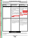
LED 9 is ON 32 VAC power is being supplied to
the firing board from leads #207 and
#208 connected to the phase angle
winding in the Main Transformer.
LED 9 is not lit or is dimmer than The proper AC power may not be
the other LEDs reaching the firing board. Check for
loose or faulty connections. Perform
the Main Transformer Test.
LED 10 is ON This indicates the trigger circuit is
activated at the 14-pin receptacle or
the terminal strip or that the Output
Terminal Switch (SW5) is closed.
TABLE F.1 - LED 7, 8, 9 AND 10