WELDING PERFORMANCE
LOW INDUCTANCE TERMINAL
The inside right Negative (-) terminal is lower choke
inductance and presently is only recommended for
welding with NR203Ni 1% procedures. All other
processes are to be welded using the outside right
Negative (-) terminal with higher choke inductance.
CV MODE CURRENT-LIMITING
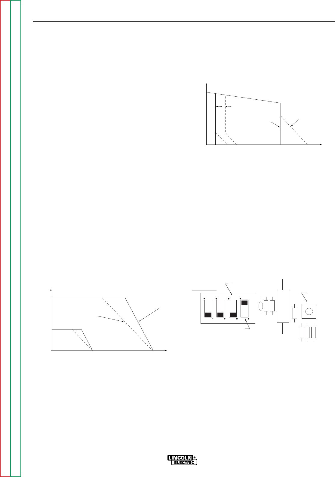
CV MIG and CV Sub-Arc modes employ electronic
current limiting to limit excessive short circuit output
current which can result in undesirable arc character-
istics or nuisance over current protection shutdown
(see Machine Protection section).
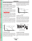
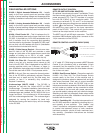
As shipped, the DC-655 is set for “Hi” current limiting,
which maintains constant voltage until the welding
current exceeds a level proportional to the voltage set-
ting, then falls off linearly at about 10 volts per 100
amps to a limited short circuit current. “Lo” current
limiting provides the same short circuit current, but the
arc voltage begins to linearly fall off at lower current, at
about 5 volts per 100 amps.
“Hi” is recommended for all CV processes, especially
for CV subarc and CV arc gouging, but “Lo” tends to
“soften” the arc more when welding NR203Ni 1% on
the Low Inductance (-) terminal. If “Lo” is desired,
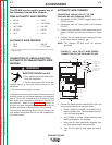
switch #4(right-most) of the DIP switch located on the
lower-center of the DC-655 Control PC board needs to
be switched from up (Hi) position to down (Lo) posi-
tion.
CC MODE ARC FORCE
Arc Force provides extra weld current which linearly
increases as the welding voltage decreases below a
level determined by the constant current setting. The
Arc Force control knob, located behind the latched
cover, adjust Arc Force from “Min” (no current
increase) to “Max” (about 9A/V increase).
As a general guideline for CC welding, set Arc Force to
“Mid” position and increase (typically to no more than
#7) as necessary to prevent “stubbing” or “pop-outs”
while welding. This higher arc force is recommended
especially for low end 6010 stick welding.
CC MODE HOT START
Hot start is built-in for CC mode stick and carbon arc
starting. Hot Start provides an extra weld current
“boost” at the arc strike which increases with higher
current settings. This Hot Start level exponentially
decays to the weld current setting in a few seconds.
Adjustment of the Hot Start shouldn’t be necessary,
but an unsealed trimmer (R81) is provided on the DC-
655 Control PC Board to adjust hot start. Full counter-
clockwise adjustment will reduce Hot Start to zero.
CC MODE ARC GOUGING
The DC-655 is rated for air carbon arc gouging with up
to 3/8” (10mm) diameter carbons. CC mode gouging
is often preferred over CV mode for cutting control, but
some Arc Force may be required to avoid carbon stub-
bing.
OPERATION
B-8 B-8
IDEALARC DC-655
Return to Section TOC Return to Section TOC Return to Section TOC Return to Section TOC
Return to Master TOC Return to Master TOC Return to Master TOC Return to Master TOC
VOLTS
AMPS
CV OUTPUT
"HI" Current Limit
"Lo" Current Limit
High
Setting
Low
Setting
VOLTS
AMPS
CC OUTPUT
Min. Arc Force
Hot Start
OCV
Low
Setting
Hi
Setting
Max. Arc Force
1 2 3 4
Switch #4 "Hi"CV Current
Limit (as shown)
DIP Switch
See Machine Shutdown section
for use of switch #1 and #2.
Note:
CC Hot Start
Trimmer
DC-655 Control PC Board
Switch #3 is for test
purposes. Keep down.
(as shown)


