


Return to Section TOC Return to Section TOC Return to Section TOC Return to Section TOC
Return to Master TOC Return to Master TOC Return to Master TOC Return to Master TOC
TROUBLESHOOTING & REPAIR
F-33 F-33
IDEALARC DC-655
INPUT CONTACTOR TEST (continued)
TEST PROCEDURE
1. Disconnect the main input supply power to
the machine.
2. With the 3/8” nut driver, remove the case top
and input access cover.
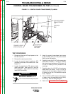
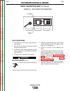
3. Locate the three leads connected to the
input contactor coil (X1/#256 and #255A).
See Figure F.12.
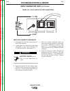
4. Connect an AC voltmeter to the leads.
ELECTRIC SHOCK can kill.
• Do not touch electrically hot parts.
5. Apply the correct three-phase input power
to the DC-655 and turn the power switch
(SW1) to the ON position.
6. Check for 120 VAC at the contactor coil
leads.
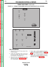
7. If the 120 VAC is NOT present, with the input
power switch (SW1) on, check the switch
and associated circuitry. See the Wiring
Diagram. Also see the Control Board LED
Chart. Relay CR2 may be faulty. See the
Wiring Diagram. Perform the Control
Transformer (T2) Test.
8. If the 120 VAC IS present and the contactor
does NOT activate, the input contactor is
faulty. Replace the input contactor.
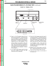
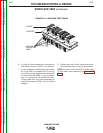
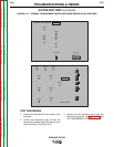
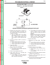
FIGURE F.12 – INPUT CONTACTOR CONNECTIONS
X1, #256
#255A
WARNING