


Return to Master TOC Return to Master TOC Return to Master TOC Return to Master TOC
TABLE OF CONTENTS
- INSTALLATION SECTION -
Section A-1 Section A-1
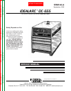
IDEALARC DC-655
Installation.............................................................................................................................Section E
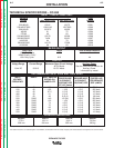
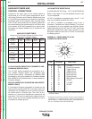
Technical Specifications - Idealarc DC-655 ...............................................................................A-2
Graphic Symbols that Appear on Rating Plate ..........................................................................A-3
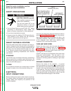
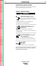
Safety Precautions......................................................................................................................A-4
Select Suitable Location.............................................................................................................A-4
Stacking................................................................................................................................A-4
Tilting....................................................................................................................................A-4
Electrical Input Connections.......................................................................................................A-4
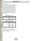
Fuse and Wire Sizes.............................................................................................................A-4
Ground Connection..............................................................................................................A-4
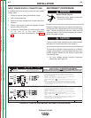
Input Power Supply Connections ........................................................................................A-5
Reconnect Procedure.................................................................................................................A-5
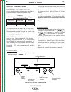
Output Connections ...................................................................................................................A-6
Electrode and Work Cables..................................................................................................A-6
Auxiliary Power and Control Connections ...........................................................................A-7
Auxiliary Power Table.....................................................................................................A-7
115VAC Duplex Receptacle...........................................................................................A-7
230V Receptacle............................................................................................................A-7
14 Pin MS Type Receptacle...........................................................................................A-7
Terminal Strips ...............................................................................................................A-8