


TROUBLESHOOTING & REPAIR
F-55 F-55
IDEALARC DC-655
Return to Section TOC Return to Section TOC Return to Section TOC Return to Section TOC
Return to Master TOC Return to Master TOC Return to Master TOC Return to Master TOC
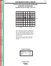
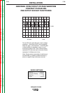
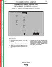
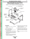
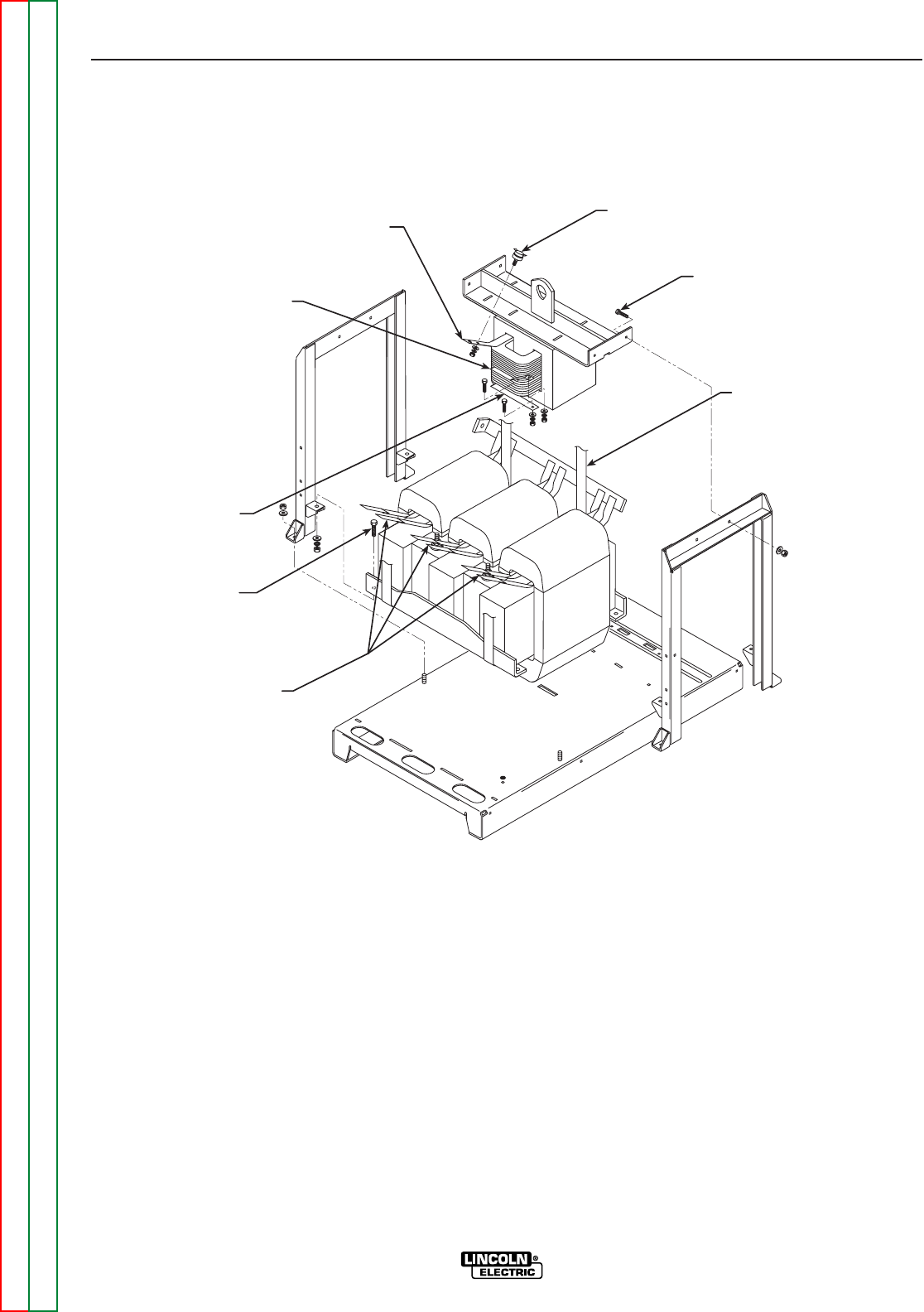
FIGURE F.21 – OUTPUT CHOKE/MAIN TRANSFORMER ASSEMBLY DETAILS
CHOKE THERMOSTAT
(LEADS #273 AND 41A)
CHOKE / FRAME
MOUNTING
BOLTS (4)
ROPE SLING
TOP LEAD (#222A)
CENTER TAP
(LOW INDUCTANCE
OUTPUT LEAD)
BOTTOM CHOKE
LEAD (HIGH
INDUCTANCE
OUTPUT LEAD)
IRON/COIL
MOUNTING
BOLTS (4)
TRANSFORMER
SECONDARY
LEADS (6)
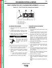
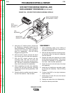
MAIN TRANSFORMER AND CHOKE REMOVAL
AND REPLACEMENT PROCEDURE (continued)
PROCEDURE
1. Remove the input power to the DC-655
machine.
2. Remove the case top and sides.
OUTPUT CHOKE REMOVAL
3. Label and remove leads #273 and 41A from
the choke thermostat.
4. Using the 9/16” wrench, remove the flexible
transformer secondary lead and the #222A
lead from the top lead of the output choke.
See Figure F.21.
5. Using the 9/16” wrench, remove the low
inductance output lead from the center tap
of the choke. See Figure F.21.
6. Using the 9/16” wrench, remove the high
inductance output lead from the bottom
choke lead. See Figure F.21.
7. Support the choke with a crane or hoist.
8. Using the 9/16” wrench, remove the four
bolts, washers and nuts mounting the choke
assembly to the transformer frame assem-
bly.
9. Carefully lift the choke from the DC-655
machine.