


Return to Section TOC Return to Section TOC Return to Section TOC Return to Section TOC
Return to Master TOC Return to Master TOC Return to Master TOC Return to Master TOC
TROUBLESHOOTING & REPAIR
F-26 F-26
IDEALARC DC-655
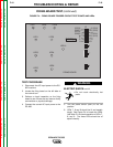
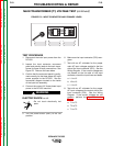
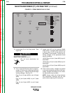
15. Locate plug J5 on the firing board. See
Figure F.9.
ELECTRIC SHOCK can kill.
• Do not touch electrically hot
parts.
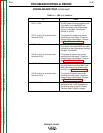
16. Turn on the DC-655 and check for approx-
imately 32 VAC at the following leads and
pins at plug J5. These are the phase angle
winding voltages. See Fig. F.9.
Plug J5 pin-15 (lead #203) to pin-16 (lead
#204)
Plug J5 pin-8 (lead #205) to pin-7 (lead
#206)
Plug J5 pin-6 (lead #207) to pin-5 (lead
#208)
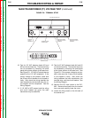
17. Locate plug J13 on the optional digital
meter board. If a digital meter board is not
in place, plug J13 will not be used but will
be present in the harness. Check the fol-
lowing voltages at the appropriate leads
and pin locations.
10 VAC Plug J13 pin-1 (lead #331) to pin-2
(lead #332)
10 VAC Plug J13 pin-4 (lead #333) to pin-5
(lead #334)
42 VAC Plug J13 pin-3 (lead #335) to pin-6
(lead #336)
18. If the correct primary voltages are applied
to the main transformer and any of the sec-
ondary voltages are missing or not correct,
the transformer may be faulty.
NOTE: Always check the wiring between
the transformer windings and the test
points before replacing the transformer.
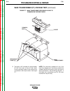
MAIN TRANSFORMER (T1) VOLTAGE TEST (continued)
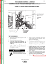
FIGURE F.9 - FIRING BOARD PLUG J5 PINS
FIRING BOARD
G2699-[ ]
16 (204)
15 (203)
14
13 (231)
12 (215)
11
10
9
(205) 8
(206) 7
(207) 6
(208) 5
4
3
2
1
LED7 LED8 LED9
LED1
LED2
LED3
LED4
LED5
LED6
LED10
J5
J6
J7
J4
WARNING