


TROUBLESHOOTING & REPAIR
F-56 F-56
IDEALARC DC-655
Return to Section TOC Return to Section TOC Return to Section TOC Return to Section TOC
Return to Master TOC Return to Master TOC Return to Master TOC Return to Master TOC
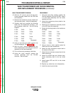
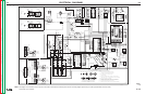
MAIN TRANSFORMER AND CHOKE REMOVAL
AND REPLACEMENT PROCEDURE (continued)
MAIN TRANSFORMER REMOVAL
10. With the 1/2” wrench, remove the six trans-
former secondary leads from the SCR heat
sink assembly.
11. Remove the transformer primary leads from
the reconnect panel. Label for reassembly.
12. Carefully label and unsolder the following
leads from the transformer windings. Cut
any necessary cable ties. See the Wiring
Diagram.
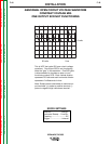
❒ 335 ❒ 203 ❒ 31
❒ 336 ❒ 204 ❒ 32A
❒ 331 ❒ 205 ❒ 41
❒ 332 ❒ 206 ❒ 42A
❒ 333 ❒ 207 ❒ 41
❒ 334 ❒ 208
thermostat
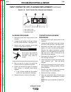
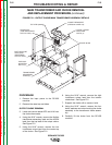
13. Using a rope sling and hoist, support the
iron/coil assembly. See Figure F.21.
14. With the 9/16” wrench, remove the four
bolts, washers and nuts holding the iron/coil
assembly to the frame assembly.
15. Cut or remove any necessary cable ties.
16. Using the hoist, carefully remove the
iron/coil assembly from the DC-655
machine. Clear all leads.
REASSEMBLY
1. Using the rope sling, carefully position the
iron/coil assembly onto the DC-655. Mount
it to the frame assembly with four bolts,
washers and nuts.
2. Attach the transformer primary leads to the
reconnect panel.
3. Attach the six transformer secondary leads
to the SCR heat sink assembly.
4. Solder the following leads to the transformer
windings.
❒ 335 ❒ 203 ❒ 31
❒ 336 ❒ 204 ❒ 32A
❒ 331 ❒ 205 ❒ 41
❒ 332 ❒ 206 ❒ 42A
❒ 333 ❒ 207 ❒ 41
❒ 334 ❒ 208
thermostat
5. Using a crane or hoist, carefully place the
choke onto the main transformer.
6. Attach the high inductance output lead to
the bottom choke lead.
7. Attach the low inductance output lead to the
choke center tap.
8. Attach the #222A lead and flexible trans-
former secondary lead to the top choke
lead.
9. Attach leads #273 and 41A to the choke
thermostat.
10. Replace any cable ties cut at disassembly.
11. Install the case top and sides.