


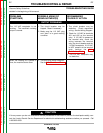
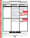
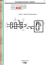
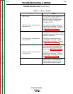

4. Check for the presence of 42 VAC at the ter-
minal strip ( #2 to #41). See the Simplified
Trigger Diagram.
5. If 42 VAC is not present at the terminal strip,
check the circuit breaker and leads #42A
and #41 at the P15 connector. See the
Simplified Trigger Diagram. Also perform
the Main Transformer Test.
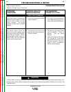
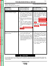
6. Remove the main input supply power to the
DC-655 machine.
7. Check continuity (zero ohms) from lead
#42A ( plug P15 pin-13) to lead #2 at the 14-
pin receptacle pin “C”. Also check continu-
ity to the output terminal switch. See the
Simplified Trigger Diagram. If a resistance
of any value is indicated, check the associ-
ated wires and plugs.
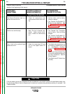
8. Check continuity (zero ohms) from pin “D”
(lead #4) at the 14-pin receptacle to the out-
put terminal switch and also to plug J5-pin
9 at the firing board. See the Simplified
Trigger Diagram and Figures F. 1 and F.2. If
a resistance of any value is indicated, check
the associated wires and plugs.
TROUBLESHOOTING & REPAIR
F-15 F-15
IDEALARC DC-655
Return to Section TOC Return to Section TOC Return to Section TOC Return to Section TOC
Return to Master TOC Return to Master TOC Return to Master TOC Return to Master TOC
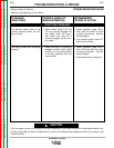
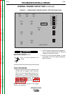
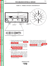
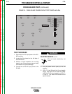
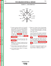
POSITIVE
OUTPUT
TERMINAL
LOW INDUCTANCE
NEGATIVE OUTPUT
TERMINAL
HIGH INDUCTANCE
NEGATIVE OUTPUT
TERMINAL
TERMINAL STRIP
COVER PANEL
14 PIN MS RECEPTACLE
+21
-21 41 4 2 31 32 75 76
77
TERMINAL STRIP
J=31
I=41
N
H=21
G=75
M
E=77
D=4
C=2
L
B=GND
A=32
K=42
F=76
FIGURE F.2 – TERMINAL STRIP AND 14-PIN RECEPTACLE