


Return to Section TOC Return to Section TOC Return to Section TOC Return to Section TOC
Return to Master TOC Return to Master TOC Return to Master TOC Return to Master TOC
TROUBLESHOOTING & REPAIR
F-52 F-52
IDEALARC DC-655
PROCEDURE
1. Remove the input power to the DC-655
machine.
2. Using the 3/8” wrench, remove the case top
and sides.
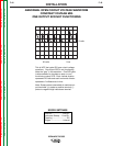
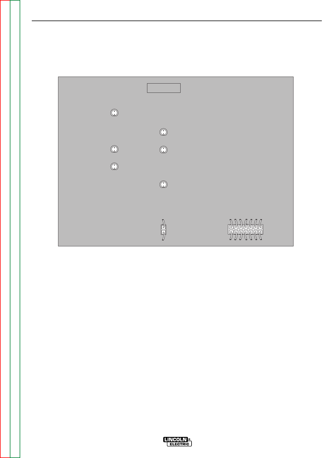
3. Locate and remove plugs J9 and J20 from
the Thermal Fan/Snubber Board. See Figure
F.19.
4. Disconnect lead #222 from the negative high
inductance output terminal. This lead runs
from plug J9 to the negative high inductance
output terminal. Cut any necessary cable
ties. See the Wiring Diagram.
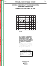
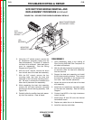
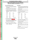
SCR RECTIFIER BRIDGE REMOVAL AND
REPLACEMENT PROCEDURE (continued)
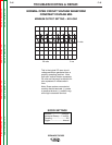
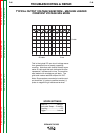
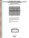
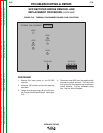
THERMAL FAN / SNUBBER
LED5
LED1
LED2
LED3
LED4
LED6
PLUG J9
L10124-[ ]
PLUG J20
FIGURE F.19 - THERMAL FAN/SNUBBER BOARD PLUG LOCATIONS