


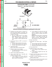

TEST FOR CONTACT CONTINUITY
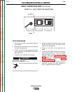
1. Disconnect the main input supply power to
the DC-655 machine.
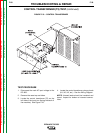
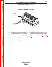
2. Locate, label and remove the three leads
connected to the input contactor coil
(X1/#256 and #255A). See Figure F.13.
ELECTRIC SHOCK can kill.
• Do not touch electrically hot
parts.
3. Using the external 120 VAC supply, apply
120 VAC to the terminals of the input con-
tactor coil. If the contactor does NOT acti-
vate, the input contactor is faulty.
4. With the contactor activated, check the
continuity across the contacts. (Zero ohms
or very low resistance is normal.) See
Figure F.13. If the resistance is high, the
input contactor is faulty. Replace the input
contactor.
5. When the contactor is NOT activated, the
resistance should be infinite or very high
across the contacts. If the resistance is
low, the input contactor is faulty. Replace
the input contactor.
TROUBLESHOOTING & REPAIR
F-34 F-34
IDEALARC DC-655
Return to Section TOC Return to Section TOC Return to Section TOC Return to Section TOC
Return to Master TOC Return to Master TOC Return to Master TOC Return to Master TOC
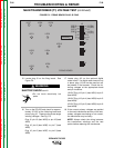
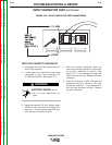
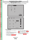
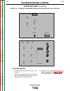
#256
#255A
#255A
X1, #256
FIGURE F.13 – INPUT CONTACTOR TEST CONNECTIONS
INPUT CONTACTOR TEST (continued)
WARNING