


CONTROL BOARD, FIRING BOARD,
SNUBBER/FAN, BOARD AND
RECTIFICATION
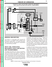
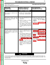
The “neutrals” of the welding secondary windings in
the main transformer are connected together, and the
six starts are connected to the six Silicon Controlled
Rectifier (SCR) assemblies to form a six-phase output.
This six-phase AC output from the main transformer
secondary is rectified and controlled through the SCR
bridge.
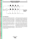
A portion of the firing board is a three-phase circuit.
Each phase provides two firing pulses, one for each of
the two SCRs controlled by that phase. When a gate
firing enable signal is received, the firing circuit sup-
plies the proper amount of energy to the gates of the
power SCRs. When this gate firing signal is applied at
the correct time, through the snubber/fan board, the
SCR will turn ON. The amount of ON time versus OFF
time determines the output of the machine. See SCR
Operation. At this time the latching resistor is brought
into the machine’s output circuit. The latching resistor
provides a pre-load for the SCR bridge.
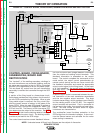
The control board receives current feedback informa-
tion from the shunt and voltage feedback information
from the choke and welding output terminals. This
feedback information is processed on the control
board. The control compares the commands of the
mode switch, the output control potentiometer (or
remote control device) and the arc force control with
the feedback information and sends the appropriate
output control signal to the firing board. In the event
of a “fault condition,” the control board activates the
fault relay (CR2). See Protective Devices and Shut
Down Circuits.
A tapped output choke is connected between the neu-
tral connection of the main transformer secondaries
and the two negative output terminals. This large
inductor stores energy, which provides current filtering
for the welding output of the DC-655. Two negative
output terminals are provided. One is connected to
the tap lead in the choke, thus providing a lower induc-
tance. The other utilizes the entire choke for higher
inductance arc characteristics.
The snubber/fan board furnishes protection to the
SCR bridge from the transient voltages. It also moni-
tors the thermal sensor and activates the fan motor
when cooling is necessary.
THEORY OF OPERATION
E-3 E-3
IDEALARC DC-655
Return to Section TOC Return to Section TOC Return to Section TOC Return to Section TOC
Return to Master TOC Return to Master TOC Return to Master TOC Return to Master TOC
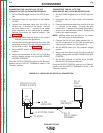
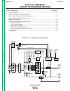
NOTE: Unshaded areas of Block Logic Diagram are the subject of discussion.
FIGURE E.3 – CONTROL BOARD, FIRING BOARD, SNUBBER/FAN BOARD AND RECTIFICATION
CONTROL
TRANSFORMER
R
E
C
O
N
N
E
C
T
CONTACTOR
FAULT PROTECTION
115VAC
MAIN
TRANSFORMER
CONTROL
BOARD
SHUNT
OUTPUT
CONTROL
MODE
SWITCH
POSITIVE
TERMINAL
NEGATIVE
TERMINAL
LATCHING
RESISTOR
F
E
E
D
B
A
C
K
F
E
E
D
B
A
C
K
SCR BRIDGE
42VAC
115VAC
42VAC
T
E
R
M
I
N
A
L
S
T
R
I
P
TO OPTIONAL
METER BOARD
HIGH
LOW
ARC FORCE
CONTROL
FIRING
BOARD
SNUBBER
FAN
BOARD
CR2
CONTROL
BOARD
TRANSFORMER
CR1
CHOKE
14-pin
Amphenol
115VAC
Receptacle
Fan
Motor Fan
Thermal
Sensor
42VAC 10VAC
10VAC
32VAC
32VAC
32VAC
SIGNAL
G
A
T
E
S
I
G
N
A
L
GATE
SIGNAL
OUTPUT
CONTROL