


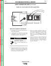

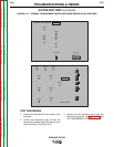

4. Construct the circuit shown in Figure F.17.
One 6-volt lantern battery can be used. Set
the voltmeter scale low, at approximately 0-
5 volts or 0-10 volts.
a. Test the voltage level of the battery.
Short leads (A) and (C). Close switch
SW-1. Battery voltage should be 4.5
volts or higher. If lower, replace the bat-
tery.
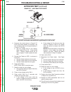
5. Connect the Tester to SCR 1 as shown in
Figure F.17.
a. Connect Tester lead (A) to the anode.
b. Connect Tester lead (C) to the cathode.
c. Connect Tester lead (G) to the gate.
6. Close switch SW-1.
NOTE: Switch SW-2 should be open.
7. Read the meter for zero voltage.
a. If the voltage reading is higher than zero,
the SCR is shorted.
8. Close or keep closed switch SW-1.
9. Close switch SW-2 for 2 seconds and
release and read the meter.
a. If the voltage is 3-6 volts while the
switch is closed and after the switch is
open, the SCR is functioning.
b. If the voltage is 3-6 volts only when the
switch is closed or there is no voltage
when the switch is closed, the SCR is
defective.
NOTE: Be sure the battery is functioning
properly. A low battery can affect the
results of the test. Repeat the battery
test procedure in Step 4 if needed.
10. Open switch SW-1.
11. Reconnect the Tester leads. See Figure
F.17.
a. Connect Tester lead (A) to the cathode.
b. Connect Tester lead (C) to the anode.
c. Disconnect Test lead (G) from the gate.
12. Close switch SW-1.
13. Read the meter for zero voltage.
a. If the voltage is zero, the SCR is func-
tioning.
b. If the voltage is higher than zero, the
SCR is shorted.
14. Perform the Active Test Procedure outlined
in Steps 5-13 for SCRs 2-6.
15. Replace all SCR assemblies that do not
pass the above tests.
16. Plug J9 onto the thermal fan/snubber board
and plug J5 into the firing board.
TROUBLESHOOTING & REPAIR
F-40 F-40
IDEALARC DC-655
Return to Section TOC Return to Section TOC Return to Section TOC Return to Section TOC
Return to Master TOC Return to Master TOC Return to Master TOC Return to Master TOC
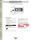
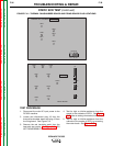
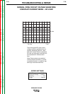
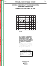
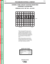
ACTIVE SCR TEST (continued)
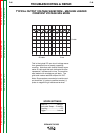
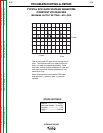
FIGURE F.17 – HEAT SINK TEST POINTS
ANODE
CATHODE
SW1
R2
SW2
+
V
R1
G
C
A
SCR
UNDER
TEST
6 VOLT
LANTERN
BATTERY
R1 = 4 ohms/10 watts
R2 = 3 ohms/10 watts
To test SCRs construct the circuit outlined above. Resistor values are plus or minus
ten precent. The voltmeter scale should be low, approximately 0-5 or 0-10 volts DC.