


The DC-655 can be used to power any of
the following Lincoln Wire feeders:
SEMI-AUTOMATIC WIRE FEEDERS
• DH-10 • LN-9*
• LN-10 • LN-9 GMA*
• LN-7 GMA* • LN-23P
• LN-742 • LN-25
• LN-7* • LN-8*
AUTOMATIC WIRE FEEDERS*
• NA-3 • NA-5R
• NA-5 • LT-7 Tractor
* European DC-655 models only provide 115VAC for these feeders at the ter-
minal strip (TS2)
CONNECTION OF LINCOLN ELECTRIC
AUTOMATIC OR SEMIAUTOMATIC WIRE
FEEDERS
ELECTRIC SHOCK can kill.
• Only qualified personnel should per-
form this installation.
• Turn the input power OFF at the dis-
connect switch or fuse box before working on this
equipment.
• Do not touch electrically hot parts.
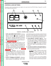
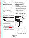
Auxiliary power for wire feeder operation is available at
both a 14-pin MS receptacle and at terminal strips
with screw-type connections located on the front of
the machine. Refer to the Installation section for
pinouts and lead designations. The two circuits are
isolated, and each is protected by a circuit breaker.
The following descriptions show how to connect the
wire feeders using either the 14-pin MS receptacle or
the terminal strip.
AUTOMATIC WIRE FEEDERS
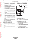
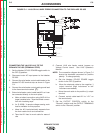
CONNECTING THE NA-3 OR LT-7 TO THE
IDEALARC DC-655 (TERMINAL STRIP)
1. Set Idealarc DC-655 POWER toggle switch to the
OFF (0) position.
2. Disconnect main AC input power to the Idealarc
DC-655.
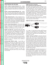
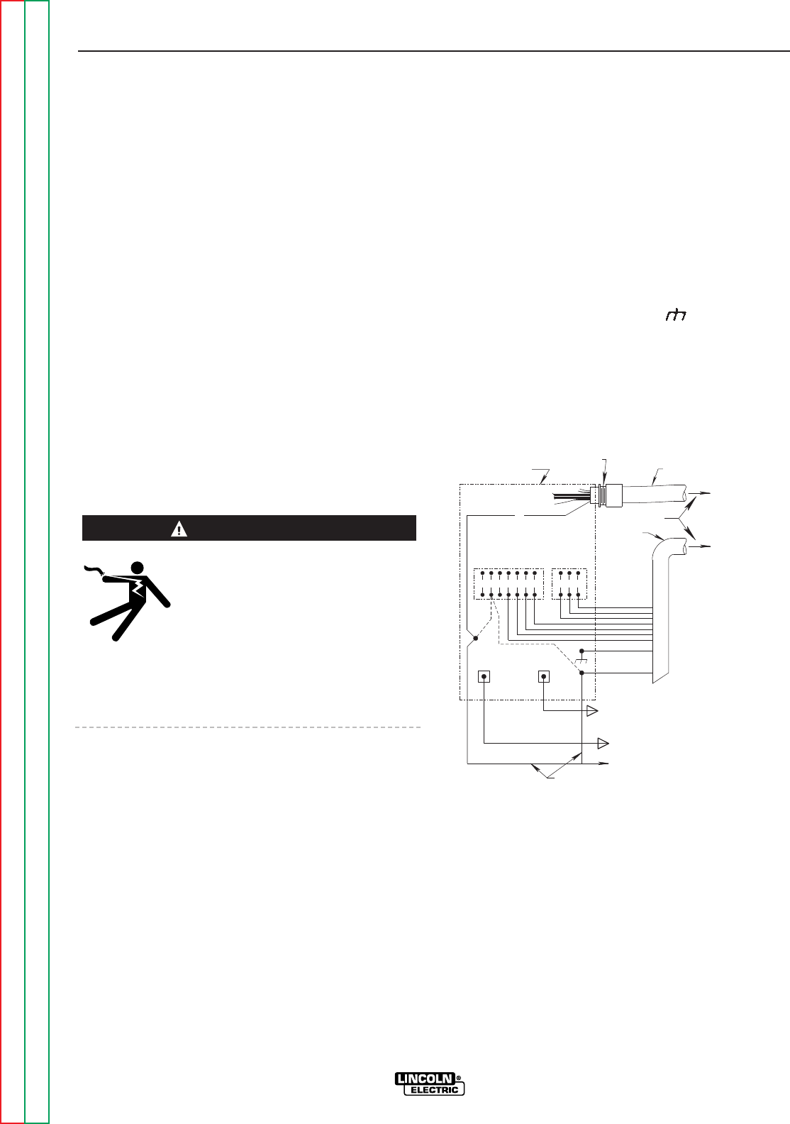
3. Connect the wire feeder control cable leads to the
Idealarc DC-655 terminal strip as shown in Figure
C.1.
4. Connect the wire feeder control cable ground lead
to the frame terminal marked .
NOTE: The Idealarc DC-655 must be properly
grounded.
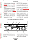
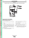
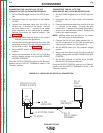
FIGURE C.1 – NA-3 OR LT-7 WIRE FEEDER
CONNECTION TO THE IDEALARC DC-655
5. Extend wire feeder control cable lead #21 so it can
be connected directly to the work piece.
a. Make a bolted connection using AWG #14 or
larger insulated wire. Tape the bolted connec-
tion with insulating tape.
b. An S-16586- X remote voltage sensing work
lead is available for this purpose.
c. Keep the #21 lead electrically separate from
the work cable circuit and connection.
d. Tape the #21 lead to work cable for ease of
use.
ACCESSORIES
C-3 C-3
IDEALARC DC-655
Return to Section TOC Return to Section TOC Return to Section TOC Return to Section TOC
Return to Master TOC Return to Master TOC Return to Master TOC Return to Master TOC
WARNING
NEGATIVE
POSITIVE
32
31
2
4
GND
21
ELECTRODE CABLE
TO WORK
POWER SOURCE
CONTROL BOX
21
FOR CONTROL CABLE
WITH 14 PIN MS-TYPE
PLUG CONNECTOR
OR
FOR CONTROL CABLE
WITH TERMINAL STRIP
LEAD CONNECTORS
CONTROL CABLE
14-PIN
RECEPTACLE
75
76
77
TO AUTOMATIC
EQUIPMENT
TO AUTOMATIC
CONTROL CABLE
41
4 2 31
32
75 76
77
21
-
21
+
REMOTE VOLTAGE SENSING LEAD