


Return to Section TOC Return to Section TOC Return to Section TOC Return to Section TOC
Return to Master TOC Return to Master TOC Return to Master TOC Return to Master TOC
TROUBLESHOOTING & REPAIR
F-28 F-28
IDEALARC DC-655
CONTROL TRANSFORMER (T2) TEST (continued)
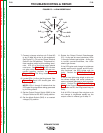
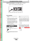
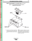
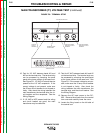
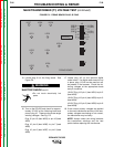
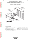
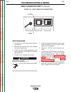
FIGURE F.10 – CONTROL TRANSFORMER
TEST PROCEDURE
1. Disconnect the main AC input voltage to the
DC-655.
2. Remove the case top and sides.
3. Locate the control transformer (T2) on the
left side of the input box (facing the back of
the machine). See Figure F.10.
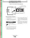
4. Locate the control transformer primary leads
(H1, H2, H3, etc.). See the Wiring Diagram.
NOTE: Unused leads should be insulated and
taped. Inspect for broken or incorrect connec-
tions.
211