


Return to Section TOC Return to Section TOC Return to Section TOC Return to Section TOC
Return to Master TOC Return to Master TOC Return to Master TOC Return to Master TOC
TROUBLESHOOTING & REPAIR
F-23 F-23
IDEALARC DC-655
MAIN TRANSFORMER (T1) VOLTAGE TEST (continued)
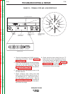
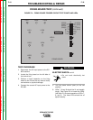
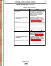
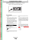
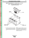
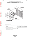
FIGURE F.6 – INPUT CONTACTOR AND PRIMARY LEADS
TEST PROCEDURE
1. Disconnect the main input power from the
DC-655.
2. Inspect the input contactor, reconnect
panel and primary leads to the main trans-
former for loose or faulty connections. See
Figure F.6. Remove the case sides.
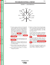
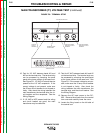
3. Confirm that the reconnect panel is config-
ured correctly for the three-phase AC input
power supplied to the DC-655. See the
connection diagram located on the inside
of the input box assembly.
4. Connect the correct AC three-phase input
power to the DC-655 machine.
ELECTRIC SHOCK can kill.
• Do not touch electrically hot
parts.
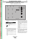
5. Turn the power switch (SW1) to the ON
position.
6. Make sure the input contactor (CR1) ener-
gizes.
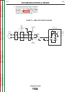
7. Test with an AC voltmeter for the proper
main AC input voltages applied to the line
side of the input contactor (CR1). See the
Wiring Diagram. If the correct voltages are
not present at the line side of the input
contactor, check the input fuses and leads.
a. L1 to L2
b. L2 to L3
c. L1 to L3
8. Test with an AC voltmeter for the proper
AC input voltages at the output side of the
input contactor (CR1). See the Wiring
Diagram. If the correct voltages are not
present, perform the Input Contactor
Test.
a. T1 to T2
b. T2 to T3
c. T1 to T3
WARNING