


TROUBLESHOOTING & REPAIR
F-42 F-42
IDEALARC DC-655
Return to Section TOC Return to Section TOC Return to Section TOC Return to Section TOC
Return to Master TOC Return to Master TOC Return to Master TOC Return to Master TOC
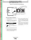
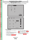
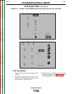
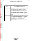
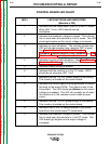
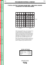
CONTROL BOARD LED CHART
LED # LED FUNCTIONS AND INDICATIONS
(Machine is ON)
1 Indicates that the mode switch (SW2) is in the CC mode.
When LED 1 is on, LED 6 should also be
illuminated.
2 Indicates that feedback voltage is present. This informa-
tion is used when the machine is in a CV mode. This LED
should get brighter as the output voltage is increased.
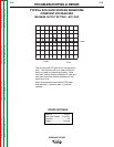
3 Indicates an input shutdown. The normally closed relay
CR2 will activate causing input contactor CR1 to open.
See Remote Control Leads Fault Protection
Shutdown, Shorted Rectifier Fault Protection and Idle
Shutdown Timer in the Operation Section.
4Indicates an over current shutdown. See Over Current
Protection Shutdown in the Operation Section.
5 Indicates output current is present.
6 Indicates that the machine is in the CC mode. LED 6
should be on whenever LED 1 is lit.
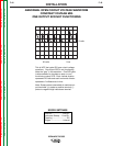
7 Indicates that the +16 VDC power supply is functioning.
This circuitry is located on the control board.
8 Indicates the control signal is being generated to control
the firing of the output SCRs. This signal is sent to the
firing board. This LED should get dimmer as the output
voltage is increased. This LED will normally be off when
the machine is in the constant current mode at open
circuit.
9 Indicates that the -10 VDC power supply is functioning.
This circuitry is located on the control board.
10 Indicates that 42 VAC is being supplied to the control
board from the control board T3 transformer.
11 Indicates that feedback voltage is present. This informa-
tion is used when the machine is in the CC mode. This
LED should get brighter as the output voltage is
increased.