


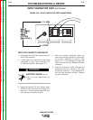

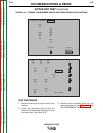

6. If a high or infinite resistance is indicated for
both steps #4 and #5, SCR1 is not shorted.
7. If a low resistance is indicated in either steps
#4 or #5, there is a shorted SCR in the out-
put rectifier bridge. Repeat steps #4 and #5
for each of the six SCRs. It may be neces-
sary to disconnect the transformer sec-
ondary leads from the rectifier assembly to
isolate the defective SCR(s). See the Wiring
Diagram.
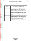
8. Replace plug J9 into the thermal fan/snub-
ber board and plug J5 into the firing board.
NOTE: To further check the SCRs’ functions use
an SCR tester and proceed to the Active SCR
Test.
TROUBLESHOOTING & REPAIR
F-37 F-37
IDEALARC DC-655
Return to Section TOC Return to Section TOC Return to Section TOC Return to Section TOC
Return to Master TOC Return to Master TOC Return to Master TOC Return to Master TOC
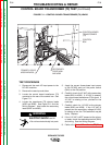
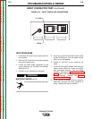
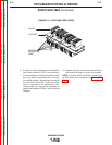
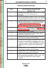
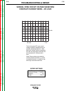
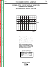
STATIC SCR TEST (continued)
FIGURE F.15 – HEAT SINK TEST POINTS
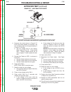
ANODE
CATHODE
REMOVE
INSULATING
PAINT